High-Performance HDPE Penstocks for Reliable Flow Control
Penstocks from Fernco are a durable, engineered solution for reliable isolation and flow regulation of water in even the most demanding environments.
Our comprehensive range of robust penstocks are manufactured from High Molecular Weight HDPE (PE500 / HMWPE) and 316 marine grade stainless steel (1.4401) as standard.
Fernco’s range of Penstocks deliver excellent corrosion resistance, UV stability, and a long service life with minimal maintenance to meet the requirements of any project.
All standard Fernco Penstocks are rated to at least 7mWC (metre water column) on and off seating. The Penstocks are manufactured to, and greatly exceed the performance requirements of, BS7775 and Class 5 of DIN16569-4.
Penstock Range
Fernco’s penstock range is a comprehensive system of products designed to meet the diverse requirements of modern water management and civil infrastructure projects. With adaptable configurations and engineered flexibility, our mounting and operational options provide a solution that integrates seamlessly into new and existing civil structures, ensuring reliability across all applications. If you are unsure which valve mounting type or how you want to operate the Penstock, use the dedicated Fernco Penstock Specification Tool.
Our Penstock Range includes:
Standard Penstocks
-
Description
-
Technical Specifications
-
Installation Guide
-
Downloads
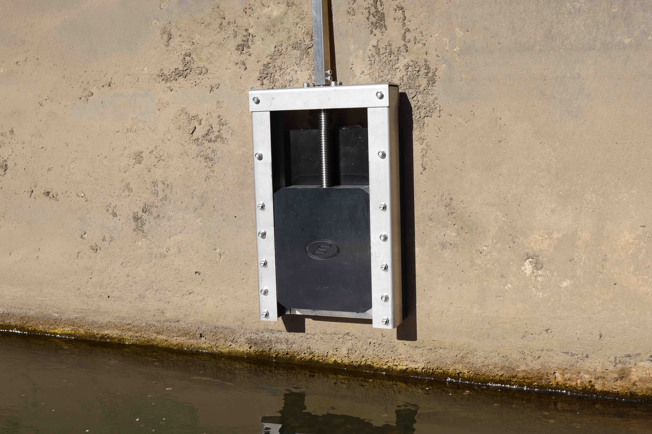
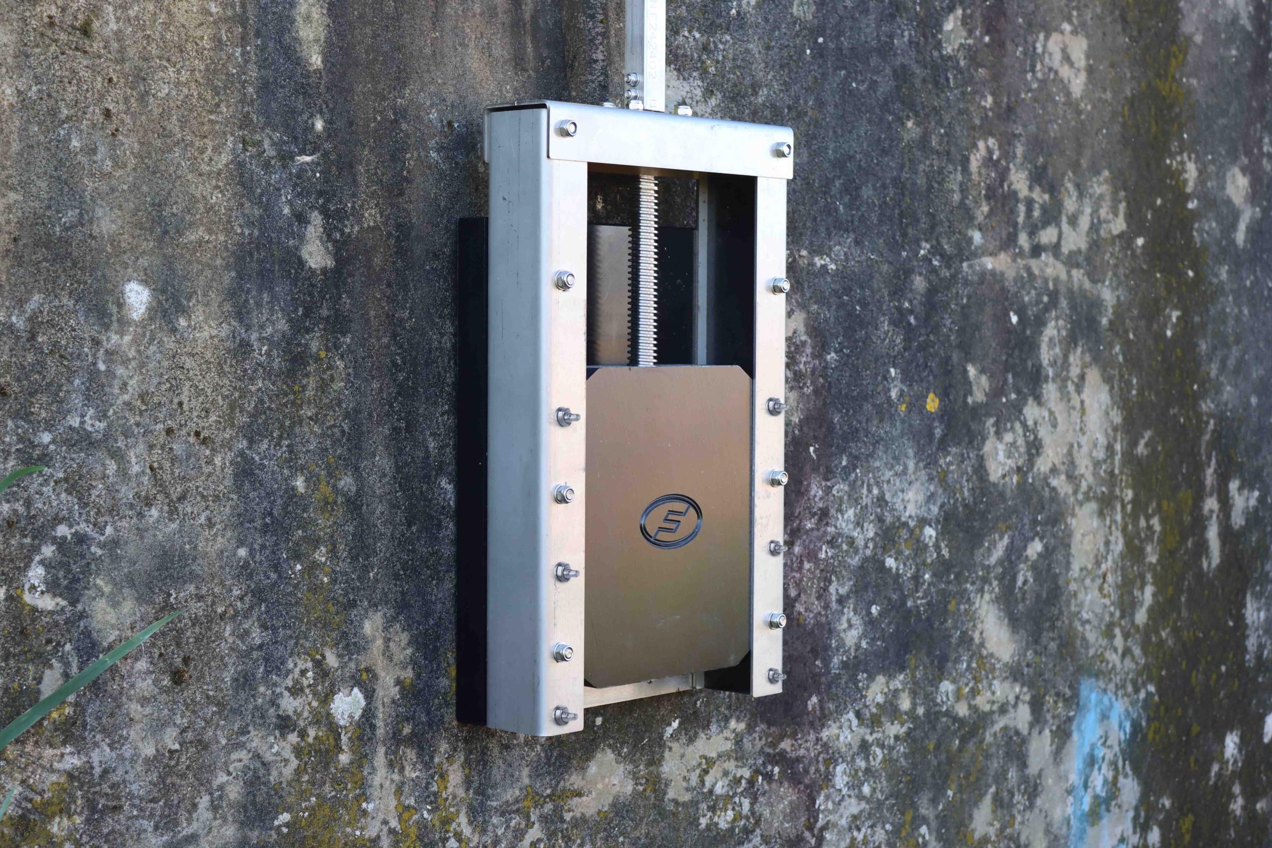
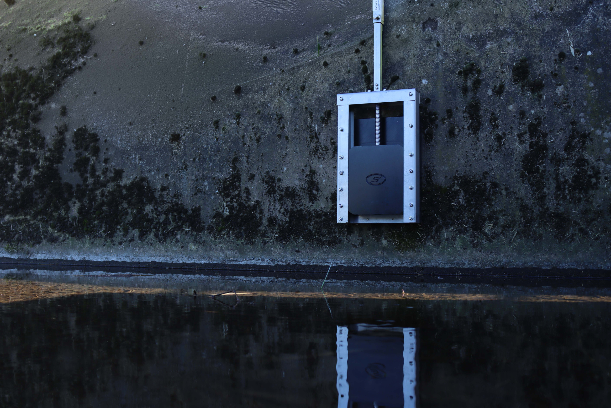
Penstocks (sometimes called water or sluice gates) control or isolate the flow of water between two areas by moving a door (gate) within a rigid frame to seal on all four sides. They are typically mounted onto headwalls or inside chambers, with the Fernco standard wall mounted non-rising spindle penstocks suitable for mounting over an orifice onto a flat surface. For applications where the mounting surface is not flat and the invert of the opening is level with the floor Fernco manufactures ranges of Curved Back and Level Invert Penstocks.
When closed, the gate compresses elastomeric resilient seals around the perimeter, achieving a mechanical, reliable isolation. HMWPE construction delivers high impact resistance and excellent corrosion resistance compared with metals or lower-grade polyethylene, while all steel components are manufactured using 1.4401 grade to provide superior durability in marine environments. The standard Fernco Penstocks are clockwise to close and supplied with a square BS Cap for T-Key operation. Unlike stoplogs or some channel penstocks, all Fernco penstocks are 4-side sealing ensuring isolation with performance that exceeds both BS7775 and DIN 19569-4 under pressures up to 7mWC off and on seating. All Fernco Penstocks are supplied with combinations of resin and mechanical setting anchors for installation.

Materials & Construction
- Backplate, side guides, and gate: HMWPE (HDPE grade PE500) for increased impact strength and durability versus industry standard PE300.
- Frame and support structure: 1.4401 Stainless Steel (316 marine grade) as standard for all internal and external steel components giving superior corrosion resistance.
- Seals: Resilient, self-adjusting EPDM seal designed for consistent compressive isolation. Nitrile or Viton seals can be supplied on request for installations with hydrocarbon or petrochemical contaminants.
- Threaded Nut: A Polyacetal (POM) nut is used as it is a “friction” material which is resistant to wear and exhibits self-lubricating properties, increasing the service life of the valve.
Drive & Operation
- Direction of closure: Clockwise to close.
- Spindle: Non-rising TR25x5 spindle as standard; rising spindle options are available.
- Spindle Cap: Supplied fitted with a BS Cap as standard for operation with a T-Key or extension spindle and hand wheel, all operational information can be found here in the Operation Guide.
- Actuation: Fernco’s range of HDPE non-rising spindle penstocks can be supplied with coded kit sets that allow for the installation and operation of the valve using a multi-turn actuator or gearbox. Link to operational guide
Performance & Compliance
- Standards: All Fernco Penstocks are manufactured to, and exceed the performance requirements of, Class 5 of DIN16569-4 and BS7775 up to 7mWC. Fernco penstocks hold a WRc approval with the assessment schedule and testing performance found in the downloads tab.
- Head loss: Full suite of head loss data is available on request.
- UV stability & corrosion resistance: Suitable for prolonged outdoor exposure and aggressive media
- Security: HDPE has almost no weigh-in value, making theft undesirable.
Environmental
- Design Life: Fernco Penstocks are adequate for a 60-year design life.
- Microplastics: HMWPE material contains at least 3% carbon black which is the most effective stabiliser for polyethylene in regard to UV degradation and increasing suitability for prolonged exposure. The carbon black absorbs light to prevent the radiation from breaking down the polymer chains and polluting the waterways with PE microplastic.

| Product Code | Diameter (Ø) | A (mm) | B (mm) | C (mm) | D (mm) | E (mm) | F (mm) | Pressure (mWC) | Weight (kg) |
|---|---|---|---|---|---|---|---|---|---|
| PS100 | 100 | 250 | 386 | 97 | 405 | 50 | 13 | 7 | 12 |
| PS150 | 150 | 300 | 486 | 97 | 505 | 50 | 13 | 7 | 16 |
| PS200 | 200 | 350 | 586 | 97 | 605 | 50 | 13 | 7 | 19 |
| PS225 | 225 | 375 | 636 | 97 | 655 | 50 | 13 | 7 | 23 |
| PS250 | 250 | 400 | 686 | 97 | 705 | 50 | 13 | 7 | 25 |
| PS300 | 300 | 450 | 786 | 97 | 805 | 50 | 13 | 7 | 30 |
| PS400 | 400 | 600 | 1123 | 97 | 1112 | 80 | 13 | 7 | 54 |
| PS500 | 500 | 700 | 1323 | 97 | 1312 | 80 | 13 | 7 | 63 |
| PS600 | 600 | 850 | 1535 | 130 | 1503 | 100 | 13 | 7 | 91 |
| PS700 | 700 | 950 | 1675 | 130 | 1642 | 100 | 13 | 7 | 117 |
| PS800 | 800 | 1050 | 1875 | 130 | 1842 | 100 | 13 | 7 | 133 |
| PS900 | 900 | 1150 | 2075 | 130 | 2042 | 100 | 13 | 7 | 158 |
| PS1000 | 1000 | 1250 | 2275 | 130 | 2242 | 100 | 13 | 7 | 177 |
| PS1050 | 1050 | 1300 | 2375 | 130 | 2342 | 100 | 13 | 7 | 187 |
Introduction
The Fernco HDPE Penstock is constructed using HDPE and Grade 316 stainless steel.
The Penstock has a vertically moving door manufactured in HDPE with stainless steel supports. The door incorporates an EPDM rubber lip seal to provide a seal against the wall plate. The gate operates within a stainless steel frame with HDPE guides.
A rubber sealing tape is secured between the frame and the mounting wall, which is compressed during installation to provide a seal.
Handling
The HDPE Penstock should only be transported when laid flat with the door plate facing upwards. It can then be lifted by means of suitable equipment.
Where chains or slings are used for handling purposes, the frame should be protected using cloth sacking or similar material.
Fully trained personnel should carry out all necessary lifting.
Storage
It is recommended to store the penstock laid down flat with the door plate facing upwards, free of dust, dirt and moisture.
Mounting Set
- Rubber sealing tape (5mm thick)
- Chemical anchor capsules
- Fixtures and accessories
Tools Required
- Appropriate PPE
- Utility knife
- Marker pen
- Suitable drill
- 12mm drill bit
- Torque wrench
- 17mm socket
- 4mm Allen key + 10mm spanner for BCSAP
- Hammer
Recommended Maximum Temperature
- Constant 80°C
- Intermittent 100°C
Penstock Installation Sequence
Before commencing installation, check the mounting wall is clean and flat. Any deformities in the wall will impede the performance of the sealing tape.
1. Marking the Mounting Face
- With suitable lifting equipment, lift the penstock and adjust it to ensure it is vertical and level.
- Check and adjust the penstock into the correct position, ensuring the invert of the pipe is flush with the invert of the penstock opening.
- Mark all of the mounting holes.
- Penstocks DN300 and over have additional mounting holes above the penstock opening. These are accessed by fully closing the penstock. Specific countersunk drop-in anchors are supplied in the mounting kits for these sizes. They are installed using an anchor setting tool (T-M10PUNCH), available separately.
- Remove the penstock.
Standard Chemical Anchor Set
- 316 Stainless Steel M10 threaded stud
- Chemical anchor capsules
- 316 Stainless Steel nuts and washers
Table 1 – Mounting Set Installation Data
| Bolt Size | Drill Bit Required | Drilled Depth | Recommended Tightening Torque |
|---|---|---|---|
| M10 | 12mm | 90mm | 8Nm |
Table 2 – Curing Time Data
| Temp °C | -15 to -10 | -9 to -5 | -4 to 0 | 1 to 5 | 6 to 10 | 11 to 20 | 21 to 30 | 31 to 40 |
|---|---|---|---|---|---|---|---|---|
| Cure Time | 30h | 16h | 10h | 45min | 30min | 20min | 5min | 3min |
2. Procedure for Installing Chemical Anchor Attachments
- Using a 12mm drill bit, drill the mounting holes to a depth of 90mm in their required positions.
- DN300 and above – Drop-in anchor installation: For the mounting holes above the door, drill to a depth of 40mm.
- Clean out the drilled holes, removing any dust or debris. Suitable eye protection must be worn.
- Insert a chemical anchor capsule into each hole.
- DN300 and above – Drop-in anchor installation: Place the anchor inside the hole and drive the anchor setting tool (or equivalent) into the anchor with a hammer until flush with the anchor base.
- Attach the M10 stud to a suitable drill.
- Place the end of the stud into the hole, then operate the drill at high speed and push the stud through the chemical anchor to the back of the hole. Once the back of the hole is reached, stop the drill to prevent resin escaping.
- Carefully remove the drill from the stud. Take care not to move the stud.
- During the curing time, proceed to placing the rubber sealing tape.
3. Placing the Rubber Sealing Tape
- Ensure that the penstock wall plate is clean and smooth.
- The sealing tape has adhesive on one side with a protective layer. Cut the tape approximately 20mm longer than required, remove the protective layer and fit it onto the frame.
- Cut the tape to length and square the corners so they connect properly.
- Drill holes through the tape using the mounting holes in the penstock as a guide.
- If installing two layers of rubber sealing tape, ensure the second layer overlaps any joints in the first layer.
4. Final Installation Steps
- Place the penstock over the studs, then place a washer and nut onto each stud and tighten by hand. If applicable, screw the corresponding threaded bolts into the anchors by hand.
- Once all nuts and washers have been placed, tighten the nuts evenly to the recommended torque. If applicable, also tighten the threaded bolts into the anchors. Countersunk bolts should be flush so that the seal does not get damaged during operation.
- All fixtures should be tightened in the recommended number pattern to 8Nm using a torque wrench. The sealing tape must be compressed evenly to ensure a good seal.
- For penstocks DN300 and above, additional anchor mounting holes must also be tightened within the number pattern, ensuring opposite mounting holes are selected sequentially.
Installation of an Extension Spindle
- Remove the BS Cap using a 4mm Allen key and a 10mm spanner.
- Place the extension spindle over the spindle of the penstock.
- Place the upper bracket 150mm below the cover level or the top of the spindle extension. Divide the remaining brackets evenly over the length of the extension spindle (one additional bracket for every 3m).
- Using the guide bracket as a template, mark on the wall where to drill for the mounting points.
- Remove the extension spindle.
- Install the brackets as required.
- Reinstall the extension spindle through the guide brackets and secure to the penstock using the bolts provided. Adjust bracket positions if necessary to ensure correct alignment.
- Fit the BSCAP in the top of the extension spindle and secure using the bolts provided. The handwheel and T-Key will also fit onto this.
Post-Installation Checks
To ensure effective operation, the following checks are recommended before leaving site:
- Check the frame is square and has not deformed.
- Clean away any debris from the penstock and ensure the invert of the orifice is clear.
- Double check all fixings are secured to the required torque.
- Check alignment of the extension spindle.
Note: Do not use excessive force when opening or closing a penstock door, as damage could occur.
When correctly installed, the penstock will provide a 60+ year life expectancy.
Maintenance Recommendations for HDPE Penstocks
- Clean the unit by hosing it down to remove grit or debris. This should be done with the gate in both the open and closed positions.
- Check that nuts and bolts are tightened to the correct torque.
- Inspect the frame, door and seals for damage.
- Check operating equipment for damage and freedom of movement, ensuring there are no worn parts.
- Check for leakage between the frame and the mounting wall. If leakage persists, remove the penstock, replace the sealing tape and reinstall.
Frequency of Inspection
The inspection frequency should be based on site conditions. In aggressive environments or locations with large amounts of silt or debris, more frequent inspections are strongly recommended.
Rising Penstocks
-
Description
-
Technical Specifications
-
Installation Guide
-
Downloads
Penstocks (sometimes called water or sluice gates) control or isolate the flow of water between two areas by moving a door (gate) within a rigid frame to seal on all four sides. They are typically mounted onto headwalls or inside manholes, with the Fernco wall mounted rising spindle penstocks suitable for mounting over a pipe outlet or square opening onto a flat surface with some clearance surrounding the orifice.
Fernco’s Penstocks are designed to meet the diverse requirements of modern water management and civil infrastructure projects. For scenarios where a visual aid of the Penstock’s gate position is required, Fernco manufactures a Rising Spindle Penstock.
When closed, the gate compresses elastomeric resilient seals around the perimeter, achieving a mechanical, reliable isolation. HMWPE construction delivers high impact resistance and excellent corrosion resistance compared with metals or lower-grade polyethylene, while all steel components are manufactured using 1.4401 grade to provide superior durability in marine environments. The rising spindle Penstocks are anticlockwise to close and supplied with a BS cap standard for T-Key operation. Unlike stoplogs or some channel penstocks, all Fernco penstocks are 4-side sealing ensuring isolation with superior performance under pressures up to 7mWC. All Fernco Penstocks are supplied with a combination of resin and mechanical setting anchors for installation.

Materials & Construction
- Backplate, side guides, and gate: HMWPE (HDPE grade PE500) for increased impact strength and durability versus industry standard PE300.
- Frame and support structure: 1.4401 Stainless Steel (316 marine grade) as standard for all internal and external steel components giving superior corrosion resistance.
- Seals: Resilient, self-adjusting EPDM seal designed for consistent compressive isolation. Nitrile or Viton seals can be supplied on request for installations with hydrocarbon or petrochemical contaminants.
- Threaded Nut: A Polyacetal (POM) nut is used as it is a “friction” material which is resistant to wear and exhibits self-lubricating properties, increasing the service life of the valve.
Drive & Operation
- Direction of closure: Anti-clockwise to close.
- Spindle: Non-rising TR25x5 spindle as standard; non-rising spindle options are available. Link to PS
- Spindle Cap: Supplied fitted with a BS Cap as standard for operation with a T-Key or extension spindle and hand wheel, all operational information can be found here in the Operation Guide.
Performance & Compliance
- Standards: All Fernco Penstocks are manufactured to, and exceed the performance requirements of, Class 5 of DIN16569-4 and BS7775 up to 7mWC. Fernco penstocks hold a WRc approval with the assessment schedule and testing performance found in the downloads tab.
- Head loss: Full suite of head loss data is available on request.
- UV stability & corrosion resistance: Suitable for prolonged outdoor exposure and aggressive media
- Security: HDPE has almost no weigh-in value, making theft undesirable.
Environmental
- Design Life: Fernco Penstocks are adequate for a 60 year design life.
- Microplastics: HMWPE material contains at least 3% carbon black which is the most effective stabiliser for polyethylene in regard to UV degradation and increasing suitability for prolonged exposure. The carbon black absorbs light to prevent the radiation from breaking down the polymer chains and polluting the waterways with PE microplastic.

| Product Code | Diameter (Ø) | A (mm) | B (mm) | C (mm) | D - open (mm) | D - closed (mm) | E (mm) | F (mm) | Pressure (mWC) | Weight (kg) |
|---|---|---|---|---|---|---|---|---|---|---|
| PSRS100 | 100 | 250 | 386 | 97 | 571 | 451 | 50 | 13 | 7 | 11 |
| PSRS150 | 150 | 300 | 486 | 97 | 721 | 551 | 50 | 13 | 7 | 16 |
| PSRS200 | 200 | 350 | 586 | 97 | 871 | 651 | 50 | 13 | 7 | 19 |
| PSRS225 | 225 | 375 | 636 | 97 | 946 | 701 | 50 | 13 | 7 | 22 |
| PSRS250 | 250 | 400 | 686 | 97 | 1021 | 751 | 50 | 13 | 7 | 24 |
| PSRS300 | 300 | 450 | 786 | 97 | 1171 | 851 | 50 | 13 | 7 | 30 |
| PSRS400 | 400 | 600 | 1123 | 97 | 1611 | 1158 | 80 | 13 | 7 | 55 |
Introduction
The Fernco HDPE Penstock is constructed using HDPE and Grade 316 stainless steel.
The Penstock has a vertically moving door manufactured in HDPE with stainless steel supports. The door incorporates an EPDM rubber lip seal to provide a seal against the wall plate. The gate operates within a stainless steel frame with HDPE guides.
A rubber sealing tape is secured between the frame and the mounting wall, which is compressed during installation to provide a seal.
Handling
The HDPE Penstock should only be transported when laid flat with the door plate facing upwards. It can then be lifted by means of suitable equipment.
Where chains or slings are used for handling purposes, the frame should be protected using cloth sacking or similar material.
Fully trained personnel should carry out all necessary lifting.
Storage
It is recommended to store the penstock laid down flat with the door plate facing upwards, free of dust, dirt and moisture.
Mounting Set
- Rubber sealing tape (5mm thick)
- Chemical anchor capsules
- Fixtures and accessories
Tools Required
- Appropriate PPE
- Utility knife
- Marker pen
- Suitable drill
- 12mm drill bit
- Torque wrench
- 17mm socket
- 4mm Allen key + 10mm spanner for BCSAP
- Hammer
Recommended Maximum Temperature
- Constant 80°C
- Intermittent 100°C
Penstock Installation Sequence
Before commencing installation, check the mounting wall is clean and flat. Any deformities in the wall will impede the performance of the sealing tape.
1. Marking the Mounting Face
- With suitable lifting equipment, lift the penstock and adjust it to ensure it is vertical and level.
- Check and adjust the penstock into the correct position, ensuring the invert of the pipe is flush with the invert of the penstock opening.
- Mark all of the mounting holes.
- Penstocks DN300 and over have additional mounting holes above the penstock opening. These are accessed by fully closing the penstock. Specific countersunk drop-in anchors are supplied in the mounting kits for these sizes. They are installed using an anchor setting tool (T-M10PUNCH), available separately.
- Remove the penstock.
Standard Chemical Anchor Set
- 316 Stainless Steel M10 threaded stud
- Chemical anchor capsules
- 316 Stainless Steel nuts and washers
Table 1 – Mounting Set Installation Data
| Bolt Size | Drill Bit Required | Drilled Depth | Recommended Tightening Torque |
|---|---|---|---|
| M10 | 12mm | 90mm | 8Nm |
Table 2 – Curing Time Data
| Temp °C | -15 to -10 | -9 to -5 | -4 to 0 | 1 to 5 | 6 to 10 | 11 to 20 | 21 to 30 | 31 to 40 |
|---|---|---|---|---|---|---|---|---|
| Cure Time | 30h | 16h | 10h | 45min | 30min | 20min | 5min | 3min |
2. Procedure for Installing Chemical Anchor Attachments
- Using a 12mm drill bit, drill the mounting holes to a depth of 90mm in their required positions.
- DN300 and above – Drop-in anchor installation: For the mounting holes above the door, drill to a depth of 40mm.
- Clean out the drilled holes, removing any dust or debris. Suitable eye protection must be worn.
- Insert a chemical anchor capsule into each hole.
- DN300 and above – Drop-in anchor installation: Place the anchor inside the hole and drive the anchor setting tool (or equivalent) into the anchor with a hammer until flush with the anchor base.
- Attach the M10 stud to a suitable drill.
- Place the end of the stud into the hole, then operate the drill at high speed and push the stud through the chemical anchor to the back of the hole. Once the back of the hole is reached, stop the drill to prevent resin escaping.
- Carefully remove the drill from the stud. Take care not to move the stud.
- During the curing time, proceed to placing the rubber sealing tape.
3. Placing the Rubber Sealing Tape
- Ensure that the penstock wall plate is clean and smooth.
- The sealing tape has adhesive on one side with a protective layer. Cut the tape approximately 20mm longer than required, remove the protective layer and fit it onto the frame.
- Cut the tape to length and square the corners so they connect properly.
- Drill holes through the tape using the mounting holes in the penstock as a guide.
- If installing two layers of rubber sealing tape, ensure the second layer overlaps any joints in the first layer.
4. Final Installation Steps
- Place the penstock over the studs, then place a washer and nut onto each stud and tighten by hand. If applicable, screw the corresponding threaded bolts into the anchors by hand.
- Once all nuts and washers have been placed, tighten the nuts evenly to the recommended torque. If applicable, also tighten the threaded bolts into the anchors. Countersunk bolts should be flush so that the seal does not get damaged during operation.
- All fixtures should be tightened in the recommended number pattern to 8Nm using a torque wrench. The sealing tape must be compressed evenly to ensure a good seal.
- For penstocks DN300 and above, additional anchor mounting holes must also be tightened within the number pattern, ensuring opposite mounting holes are selected sequentially.
Installation of an Extension Spindle
- Remove the BS Cap using a 4mm Allen key and a 10mm spanner.
- Place the extension spindle over the spindle of the penstock.
- Place the upper bracket 150mm below the cover level or the top of the spindle extension. Divide the remaining brackets evenly over the length of the extension spindle (one additional bracket for every 3m).
- Using the guide bracket as a template, mark on the wall where to drill for the mounting points.
- Remove the extension spindle.
- Install the brackets as required.
- Reinstall the extension spindle through the guide brackets and secure to the penstock using the bolts provided. Adjust bracket positions if necessary to ensure correct alignment.
- Fit the BSCAP in the top of the extension spindle and secure using the bolts provided. The handwheel and T-Key will also fit onto this.
Post-Installation Checks
To ensure effective operation, the following checks are recommended before leaving site:
- Check the frame is square and has not deformed.
- Clean away any debris from the penstock and ensure the invert of the orifice is clear.
- Double check all fixings are secured to the required torque.
- Check alignment of the extension spindle.
Note: Do not use excessive force when opening or closing a penstock door, as damage could occur.
When correctly installed, the penstock will provide a 60+ year life expectancy.
Maintenance Recommendations for HDPE Penstocks
- Clean the unit by hosing it down to remove grit or debris. This should be done with the gate in both the open and closed positions.
- Check that nuts and bolts are tightened to the correct torque.
- Inspect the frame, door and seals for damage.
- Check operating equipment for damage and freedom of movement, ensuring there are no worn parts.
- Check for leakage between the frame and the mounting wall. If leakage persists, remove the penstock, replace the sealing tape and reinstall.
Frequency of Inspection
The inspection frequency should be based on site conditions. In aggressive environments or locations with large amounts of silt or debris, more frequent inspections are strongly recommended.
Compact Penstocks
-
Description
-
Technical Specifications
-
Installation Guide
-
Downloads
For projects where 7 metres of head pressure rating is not required, or there is restricted access, Fernco manufactures a Compact Penstock for these applications. Penstocks (sometimes called water or sluice gates) control or isolate the flow of water between two areas by moving a door (gate) within a rigid frame to seal on all four sides. They are typically mounted onto headwalls or inside manholes, with the Fernco Compact penstocks suitable for mounting over a pipe outlet or square opening onto a flat surface requiring less clearance than standard penstocks. Unlike stoplogs or some channel penstocks, all Fernco Compact penstocks are 4-side sealing ensuring isolation with superior performances under pressures up to 4mWC.
When closed, the gate compresses elastomeric resilient seals around the perimeter, achieving a mechanical, reliable isolation. HMWPE construction delivers high impact resistance and excellent corrosion resistance compared with metals or lower-grade polyethylene, while all steel components are manufactured using 1.4401 grade to provide superior durability in marine environments. The non-rising spindle Penstocks are clockwise to close and supplied with a BS cap standard for T-Key operation. All Fernco Compact Penstocks are supplied with a combination of nylon fixings for installation.

Materials & Construction
- Backplate, side guides, and gate: HMWPE (HDPE grade PE500) for increased impact strength and durability versus industry standard PE300.
- Frame and support structure: 1.4401 Stainless Steel (316 marine grade) as standard for all internal and external steel components giving superior corrosion resistance.
- Seals: Resilient, self-adjusting EPDM seal designed for consistent compressive isolation. Nitrile or Viton seals can be supplied on request for installations with hydrocarbon or petrochemical contaminants.
- Threaded Nut: A Polyacetal (POM) nut is used as it is a “friction” material which is resistant to wear and exhibits self-lubricating properties, increasing the service life of the valves.
Drive & Operation
- Direction of closure: Clockwise to close.
- Spindle: Non-rising TR20x4 spindle as standard; rising spindle options are available.
- Spindle Cap: Supplied fitted with a BS square cap as standard for operation with a T-Key or extension spindles, all operational information can be found here in the Operation Guide.
Performance & Compliance
- Standards: All Fernco Penstocks are manufactured to, and exceed the performance requirements of, Class 5 of DIN16569-4 and BS7775 up to 4mWC.
- Head loss: Full suite of head loss data is available on request.
- UV stability & corrosion resistance: Suitable for prolonged outdoor exposure and aggressive media
- Security: HDPE has almost no weigh-in value, making theft undesirable.
Environmental
- Design Life: Fernco Penstocks are adequate for a 60 year design life.
- Microplastics: HMWPE material contains at least 3% carbon black which is the most effective stabiliser for polyethylene in regard to UV degradation and increasing suitability for prolonged exposure. The carbon black absorbs light to prevent the radiation from breaking down the polymer chains and polluting the waterways with PE microplastic.

| Product Code | Diameter (Ø) | A (mm) | B (mm) | C (mm) | D (mm) | E (mm) | F (mm) | Pressure (mWC) | Weight (kg) | Tightening Torque Nm |
|---|---|---|---|---|---|---|---|---|---|---|
| PSCO100 | 100 | 256 | 340 | 101 | 407 | 30 | 13 | 4 | 7 | 8 |
| PSCO150 | 150 | 306 | 440 | 101 | 507 | 30 | 13 | 4 | 9 | 8 |
| PSCO200 | 200 | 356 | 540 | 101 | 607 | 30 | 13 | 4 | 11 | 8 |
| PSCO225 | 225 | 381 | 590 | 101 | 657 | 30 | 13 | 4 | 13 | 8 |
| PSCO250 | 250 | 406 | 640 | 101 | 707 | 30 | 13 | 4 | 14 | 8 |
| PSCO300 | 300 | 456 | 740 | 101 | 807 | 30 | 13 | 4 | 17 | 8 |
1. Marking the Mounting Face
- With suitable lifting equipment, lift the Penstock into position ensuring it is vertical and level and the invert of the pipe is flush with the invert of the Penstock opening.
- Mark all the mounting holes.
- PSCO300 has additional mounting holes around the Penstock opening. These are accessed by fully opening or closing the Penstock. Shorter length (100 or 120mm) fixings are used specifically for these holes.
- Remove the Penstock.
- Using a 10mm drill bit, drill the mounting holes to a minimum depth of 95mm.
- Clean the drilled holes, removing any dust or debris. Suitable eye protection to be worn.
2. Placing the Rubber Sealing Tape
- Ensure that the Penstock wall plate is clean and smooth.
- The sealing tape has adhesive on one side with a protective layer over it. Cut the tape 20mm larger than necessary, then remove the protective layer and fit it onto the frame.
- The tape should now be cut to length and squared so that the corners connect properly.
- Drill holes through the tape by using the mounting holes in the Penstock as a guide.
- If installing two layers of rubber sealing tape, ensure the second layer overlaps any joints in the first layer.
- Tape that overhangs the wall plate can be cut if required.
For operation and maintenance guidance refer to the Penstock O&M manual and for information on accessories refer to the ancillaries datasheet, both are available on the Fernco website.
3. Final Steps
- Re-position the penstock over the pre-drilled holes.
- Push the Nylon fixing through the Penstock and into the wall ensuring the shoulder of the Nylon fixing finishes flush with the surface of the side steel.
- Insert the screws and evenly tighten all fixings to 8Nm using a torque wrench and 13mm socket.
Bespoke Penstocks
-
Description
-
Technical Specifications
Fernco offers a bespoke penstock design and manufacturing service to meet the unique requirements of complex projects. Our engineering team can design and produce penstocks in a wide range of opening shapes and sizes, ensuring precise integration with civil structures and operational needs. By adapting frame configurations and sealing systems, we deliver tailored solutions that maintain the same high standards of performance, durability, and compliance as our core range.
We can manufacture custom HDPE penstocks up to 1 metre in size and stainless steel units up to 3 metres by 2 metres, with modified frames and specialist features to suit demanding applications. Whether you require non-standard geometries, enhanced hydrostatic performance, or compatibility with automated sensor actuation systems, Fernco’s bespoke service provides a modern, engineered solution that combines flexibility with proven reliability.

Materials & Construction
- Backplate, side guides, and gate: For HDPE valves HMWPE (HDPE grade PE500) is used for increased impact strength and durability versus industry standard PE300. For fully strainless valves a welded stainless steel construction with integral u-shaped frame is used with 1.4404 or 1.4301 (316L or 304) Stainless Steel available.
- Frame and support structure: 1.4401 Stainless Steel (316 marine grade) as standard for all internal and external steel components giving superior corrosion resistance.
- Seals: Resilient, self-adjusting EPDM seal designed for consistent compressive isolation. Nitrile or Viton seals can be supplied on request for installations with hydrocarbon or petrochemical contaminants.
- Threaded Nut: For HDPE valves a Polyacetal (POM) nut is used as it is a “friction” material which is resistant to wear and exhibits self-lubricating properties, increasing the service life of the valves. A brass nut is used to compensate for the additional weight of the fully stainless steel valves.
Drive & Operation
- Direction of closure: Clockwise to close.
- Spindle: The size of the spindle will change to suit the size of the valve; rising spindle options are available.
- Actuation: Fernco’s range of HDPE non-rising spindle penstocks can be supplied with coded kit sets that allow for the installation and operation of the valve using a multi-turn actuator or gearbox. Fernco’s range of stainless steel penstocks can be supplied with all parts to allow for the installation and operation of the valve using a multi-turn actuator or gearbox. Link to operational guide
Performance & Compliance
- Standards: All Fernco Penstocks are manufactured to, and exceed the performance requirements of, Class 5 of DIN16569-4 and BS7775.
- Head loss: Full suite of head loss data is available on request.
- UV stability & corrosion resistance: Suitable for prolonged outdoor exposure and aggressive media
- Security: HDPE has almost no weigh-in value, making theft undesirable.
Environmental
- Design Life: Fernco Penstocks are adequate for a 60 year design life.
- Microplastics: HMWPE material contains at least 3% carbon black which is the most effective stabiliser for polyethylene in regard to UV degradation and increasing suitability for prolonged exposure. The carbon black absorbs light to prevent the radiation from breaking down the polymer chains and polluting the waterways with PE microplastic.
Actuating Penstocks
-
Description
-
Technical Specifications
-
Downloads
Fernco’s range of HDPE non-rising spindle penstocks can be supplied with coded kit sets that allow for the installation and operation of the valve using a multi-turn actuator or gearbox.
Actuators are driven by an electric motor allowing for remote and automated control, ideal for integration into SCADA systems. A gearbox is used to reduce the required input torque needed to operate a penstock, so that even large valves when under pressure can be easily operated by hand.
Gearboxes can be used in conjunction with actuators to reduce the size of the actuator required. All actuator accessories are manufactured using 1.4401 (316) marine grade stainless steel as standard.
Actuators and gearboxes are sized by the required input torque, if the penstock is installed in an application where 7mWC head pressure isn’t required then the actuator could be sized down to suit. For penstocks installed where the input torque exceeds 80Nm, a gearbox is advised to reduce this to a safe, operable level. A position indicator can be supplied with a gearbox or handwheel to clearly display the penstock door position.
Fernco use ISO 5210:2023 for all actuator accessories and the standard B3 keyway with a 20mm input shaft.
Torque Matrix
| Product Code | Valve DN | Penstock Opening Torque (Nm) | Number Of Turns To Open | |||||||
|---|---|---|---|---|---|---|---|---|---|---|
| 0mWC | 1mWC | 2mWC | 3mWC | 4mWC | 5mWC | 6mWC | 7mWC | |||
| PS100* | 100 | 1 | 1 | 1 | 2 | 2 | 2 | 2 | 3 | 24 1/4 |
| PS150 | 150 | 1 | 2 | 2 | 3 | 3 | 4 | 4 | 5 | 34 1/2 |
| PS200 | 200 | 1 | 2 | 3 | 4 | 5 | 6 | 7 | 8 | 44 1/4 |
| PS225 | 225 | 1 | 2 | 3 | 5 | 6 | 7 | 8 | 10 | 49 1/2 |
| PS250 | 250 | 1 | 2 | 4 | 5 | 7 | 8 | 10 | 11 | 54 1/2 |
| PS300 | 300 | 1 | 3 | 5 | 7 | 10 | 12 | 14 | 16 | 64 1/4 |
| PS400 | 400 | 2 | 6 | 10 | 13 | 17 | 21 | 25 | 29 | 90 1/4 |
| PS500 | 500 | 2 | 8 | 14 | 20 | 26 | 32 | 38 | 44 | 110 1/4 |
| PS600 | 600 | 2 | 11 | 19 | 28 | 36 | 45 | 53 | 62 | 134 3/4 |
| PS700 | 700 | 3 | 15 | 26 | 38 | 50 | 61 | 73 | 85** | 157 1/2 |
| PS800 | 800 | 3 | 18 | 34 | 49 | 64 | 79 | 95** | 110** | 180 |
| PS900 | 900 | 4 | 23 | 42 | 61 | 81** | 100** | 119** | 138** | 202 1/2 |
| PS1000 | 1000 | 4 | 28 | 51 | 75 | 99** | 123** | 147** | 170** | 225 |
* PS100 not suitable for PSACT-DM
** Gearbox recommended
Drive Mount Options
Direct Mount (PSACT-DM)
- PS150+ can be supplied with a direct mount console and keyway adapter to facilitate actuator or gearbox installation.
- The bracket is fixed to the penstock top frame providing an F10 flange interface with a 20mm shaft and B3 keyway.
- For applications where the penstock is wall mounted within a chamber or onto a headwall an actuator can be mounted directly to the penstock.
| Direct Mount Measurements Key | ||
|---|---|---|
| A | Horizontal clearance to the left of the orifice centre | 264mm |
| B | Horizontal clearance to the right of the orifice centre | 249mm |
| C | Height from direct mount bracket to top of actuator* | 418mm |
| D | Distance from penstock back plate to the spindle centre for both actuator and penstock | 64mm |
| E | Maximum distance from spindle centre out from the penstock frame | 238mm |
| F | Overall height of bracket and actuator from penstock top frame* | 471mm |
*Measurement uses AUMA SA07.2 Actuator with AM controller

Installation Instructions
- It is possible to install the Direct Mount Bracket either before or after the installation of the penstock. In most cases the direct mount bracket will be shipped affixed to the penstock top frame, so no bolting is required. If retrofitting to a valve in situ, secure the bracket to the penstock top frame using the bolts and washers provided.
- Place the keyway adapter, complete with key and cover, over the penstock spindle head and secure using M6 bolts with a washer on either side, tightening to 4Nm.
- Place an M8 washer over the M8x25 bolt and push through from underneath the penstock top frame so that the bolt thread is visible through the bracket. Place an M8 washer then an M8 spring washer before securing with an M8 Nyloc nut, tightening to 4Nm.
- Remove the keyway adapter cover, taking care not to dislodge the key.
- Lift the actuator into position over the keyway adapter, locating the key into the keyway in the actuator drive bush.
- Secure the actuator with four M10 bolts and washers.
- Check the coupling of the drive by putting the actuator into manual override and rotating the handwheel, ensuring that the penstock door moves with the actuator drive.
Pedestal Mount (PSACT-PD)
- A pedestal is used to raise the actuator or gearbox off the surface or deck level. This raises the operational height by approximately 700mm to waist height for manual override operation or maintenance.
- Uses standard F10 flange for mounting and is supplied with chemical anchors to mount the pedestal onto the floor.
- The standard penstock extension spindle (PSES) is required to raise the penstock drive keyway into the actuator drive bush within the pedestal mounting flange.
- A position indicator can be supplied with a gearbox or handwheel to display the penstock door position.
- Bespoke height pedestals can be manufactured on request.
| Pedestal Mount Measurements Key | ||
|---|---|---|
| A | Horizontal clearance to the left of the orifice centre | 264mm |
| B | Horizontal clearance to the right of the orifice centre | 289mm |
| C | Height from pedestal to top of actuator* | 418mm |
| D | Distance from penstock back plate to the spindle centre for both actuator and penstock | 64mm |
| E | Maximum distance from spindle centre out from the penstock frame | 238mm |
| F | Overall height of actuator from pedestal base* | 1021mm |
*Measurement uses AUMA SA07.2 Actuator with AM controller

Installation Instructions
- Install the penstock and extension spindle as per the standard Fernco penstock installation instructions, placing the pedestal over the spindle and finishing the extension spindle flush with the F10 flange of the pedestal.
- Place the keyway adapter, complete with key and cover, inside the end of the extension spindle and secure using M6 bolts with a washer on either side, tightening to 4Nm.
- Remove the keyway adapter cover, taking care not to dislodge the key.
Offset Mount (PSACT-OS)
- Offset mount pedestal for mounting an actuator above a penstock overhanging a flat wall.
- Can be used to mount to concrete benching in a chamber if the benching sets the valve stem too far from the wall for PSACT-CM.
- A position indicator can be supplied with a gearbox or handwheel to display the penstock door position.
| Offset Mount Measurements Key | ||
|---|---|---|
| A | Horizontal clearance to the right of the orifice centre | 264mm |
| B | Horizontal clearance to the left of the orifice centre | 289mm |
| C | Height from offset mount bracket to top of actuator* | 418mm |
| D | Distance from penstock back plate to the spindle centre for both actuator and penstock | 64mm |
| E | Maximum depth of actuator and offset bracket | 303mm |
| F | Overall height of actuator from pedestal base* | 925mm |
* Measurement uses AUMA SA07.2 Actuator with AM controller

Installation Instructions
- Install the penstock, extension spindle and guide brackets as per the standard Fernco penstock installation instructions. Place the offset mount bracket over the spindle and finish the extension spindle flush with the F10 flange of the pedestal.
- Place the keyway adapter, complete with key and cover, inside the end of the extension spindle and secure using M6 bolts with a washer on either side, tightening to 4Nm.
- Remove the keyway adapter cover, taking care not to dislodge the key.
- Lift the actuator into position over the keyway adapter, locating the key into the keyway in the actuator drive bush.
- Align both F10 flanges and secure the actuator with four M10 bolts and washers.
- Secure the base of the offset pedestal into the floor using the provided resin anchors and tighten the M12 studding to 12Nm.
- Check the coupling of the drive by putting the actuator into manual override and rotating the handwheel, ensuring that the penstock door moves with the actuator drive.
Chamber Mount (PSACT-CM)
- The penstock can be supplied with a universal wall bracket to take the load of the actuator while raising it to a suitable height for maintenance or manual operation, without needing it to be installed above the surface level.
- The bracket features a slotted F10 pad allowing for adjustment to ensure alignment with the spindle.
- Supplied with M10 studs and resin anchors for secure connection into the mounting surface.
- A position indicator can be supplied with a gearbox or handwheel to display the penstock door position if it is not easily visible from surface level.
| Chamber Mount Measurements Key | ||
|---|---|---|
| A | Horizontal clearance to the left of the orifice centre | 264mm |
| B | Horizontal clearance to the right of the orifice centre | 289mm |
| C | Height from bracket to top of actuator* | 418mm |
| D | Distance from penstock back plate to the spindle centre for both actuator and penstock | 64mm |
| E | Maximum distance from spindle centre out from the penstock frame | 238mm |
| F | Overall height of actuator from bottom edge of chamber mount bracket* | 525mm |
* Measurement uses AUMA SA07.2 Actuator with AM controller

Installation Instructions
- Install the penstock, extension spindle and guide brackets as per the standard Fernco penstock installation instructions. Place the pedestal over the spindle and finish the extension spindle flush with the F10 flange of the bracket.
- Place the keyway adapter, complete with key and cover, inside the end of the extension spindle and secure using M6 bolts with a washer on either side, tightening to 4Nm.
- Install the chamber mount adapter into the wall using the supplied resin anchors and tighten the M12 studding to 12Nm.
- Remove the keyway adapter cover, taking care not to dislodge the key.
- Lift the actuator into position over the keyway adapter, locating the key into the keyway in the actuator drive bush.
- Align both F10 flanges and secure the actuator with four M10 bolts and washers.
- Check the coupling of the drive by putting the actuator into manual override and rotating the handwheel, ensuring that the penstock door moves with the actuator drive.
Curved Back Penstocks
-
Description
-
Technical Specifications
-
Installation Guide
-
Downloads
Fernco’s Penstocks are designed to meet the diverse requirements of modern water management and civil infrastructure projects. For projects where directly mounting into a round chamber is required, Fernco’s Curved Back Penstocks are a safer & cheaper alternative to traditional benching.
Curved Back Penstocks are a durable, engineered solution for reliable isolation and flow regulation of water in even the most demanding environments. They deliver excellent corrosion resistance, UV stability, and a long service life with minimal maintenance to meet the requirements of any project. Manufactured using HMWPE (HDPE grade PE500), means they offer increased impact strength and durability versus industry standard PE300.
The Curved Back Penstock is designed to be installed directly into round chambers, removing the need for additional benching or civils work on site. They are rated to at least 7mWC (metre water column) on and off seating, while offering a solution to installation in curved chambers. They are also manufactured to, and greatly exceed the performance requirements of, BS7775 and Class 5 of DIN16569-4.

Materials & Construction
- Backplate, side guides, and gate: HMWPE (HDPE grade PE500) for increased impact strength and durability versus industry standard PE300.
- Frame and support structure: 1.4401 Stainless Steel (316 marine grade) as standard for all internal and external steel components giving superior corrosion resistance.
- Seals: Resilient, self-adjusting EPDM seal designed for consistent compressive isolation. Nitrile or Viton seals can be supplied on request for installations with hydrocarbon or petrochemical contaminants.
- Threaded Nut: A Polyacetal (POM) nut is used as it is a “friction” material which is resistant to wear and exhibits self-lubricating properties, increasing the service life of the valve.
Drive & Operation
- Direction of closure: Clockwise to close.
- Spindle: Non-rising TR25x5 spindle as standard; rising spindle options are available.
- Spindle Cap: Supplied fitted with a BS Cap as standard for operation with a T-Key or extension spindle and hand wheel, all operational information can be found here in the Operation Guide.
- Actuation: Fernco’s range of HDPE non-rising spindle penstocks can be supplied with coded kit sets that allow for the installation and operation of the valve using a multi-turn actuator or gearbox. Link to operational guide
Performance & Compliance
- Standards: All Fernco Penstocks are manufactured to, and exceed the performance requirements of, Class 5 of DIN16569-4 and BS7775 up to 7mWC. Fernco penstocks hold a WRc approval with the assessment schedule and testing performance found in the downloads tab.
- Head loss: Full suite of head loss data is available on request.
- UV stability & corrosion resistance: Suitable for prolonged outdoor exposure and aggressive media
- Security: HDPE has almost no weigh-in value, making theft undesirable.
Environmental
- Design Life: Fernco Penstocks are adequate for a 60-year design life.
- Microplastics: HMWPE material contains at least 3% carbon black which is the most effective stabiliser for polyethylene in regard to UV degradation and increasing suitability for prolonged exposure. The carbon black absorbs light to prevent the radiation from breaking down the polymer chains and polluting the waterways with PE microplastic.

| Product Code | Diameter (Ø) | Chamber Diameter Range (mm) | A (mm) | B (mm) | C (mm) | D (mm) | E (mm) | F (mm) | Pressure (mWC) | Weight (kg) |
|---|---|---|---|---|---|---|---|---|---|---|
| PSCB100-1 | 100 | 1000-1600 | 250 | 455 | 147 | 405 | 50 | 13 | 7 | 12 |
| PSCB100-2 | 100 | 1601-2100 | 250 | 455 | 137 | 405 | 50 | 13 | 7 | 12 |
| PSCB150-1 | 150 | 1000-1600 | 300 | 555 | 147 | 505 | 50 | 13 | 7 | 17 |
| PSCB150-2 | 150 | 1601-2100 | 300 | 555 | 147 | 505 | 50 | 13 | 7 | 16 |
| PSCB200-1 | 200 | 1000-1600 | 350 | 655 | 177 | 605 | 50 | 13 | 7 | 22 |
| PSCB200-2 | 200 | 1601-2100 | 350 | 655 | 147 | 605 | 50 | 13 | 7 | 21 |
| PSCB225-1 | 225 | 1000-1600 | 375 | 705 | 177 | 655 | 63 | 13 | 7 | 25 |
| PSCB225-2 | 225 | 1601-2100 | 375 | 705 | 147 | 655 | 63 | 13 | 7 | 23 |
| PSCB250-1 | 250 | 1000-1600 | 400 | 755 | 177 | 705 | 65 | 13 | 7 | 29 |
| PSCB250-2 | 250 | 1601-2100 | 400 | 755 | 177 | 705 | 65 | 13 | 7 | 28 |
| PSCB300-1 | 300 | 1000-1600 | 450 | 855 | 177 | 805 | 65 | 13 | 7 | 33 |
| PSCB300-2 | 300 | 1601-2100 | 450 | 855 | 177 | 805 | 65 | 13 | 7 | 34 |
Introduction
The Fernco HDPE Penstock is constructed using HDPE and Grade 316 stainless steel.
The Penstock has a vertically moving door manufactured in HDPE with stainless steel supports. The door incorporates an EPDM rubber lip seal to provide a seal against the wall plate. The gate operates within a stainless steel frame with HDPE guides.
A rubber sealing tape is secured between the frame and the mounting wall, which is compressed during installation to provide a seal.
Handling
The HDPE Penstock should only be transported when laid flat with the door plate facing upwards. It can then be lifted by means of suitable equipment.
Where chains or slings are used for handling purposes, the frame should be protected using cloth sacking or similar material.
Fully trained personnel should carry out all necessary lifting.
Storage
It is recommended to store the penstock laid down flat with the door plate facing upwards, free of dust, dirt and moisture.
Mounting Set
- Rubber sealing tape (5mm thick)
- Chemical anchor capsules
- Fixtures and accessories
Tools Required
- Appropriate PPE
- Utility knife
- Marker pen
- Suitable drill
- 12mm drill bit
- Torque wrench
- 17mm socket
- 4mm Allen key + 10mm spanner for BCSAP
- Hammer
Recommended Maximum Temperature
- Constant 80°C
- Intermittent 100°C
Penstock Installation Sequence
Before commencing installation, check the mounting wall is clean and flat. Any deformities in the wall will impede the performance of the sealing tape.
1. Marking the Mounting Face
- With suitable lifting equipment, lift the Curved Back Adaptor into position ensuring it is vertical, level and the invert of the pipe is flush with the invert of the Curved Back Adaptor opening.
2. Mark all the relevant mounting holes.
3. Remove the Curved Back Adaptor.
Standard Chemical Anchor Set
- 316 Stainless Steel M10 threaded stud
- Chemical anchor capsules
- 316 Stainless Steel nuts and washers
Table 1 – Mounting Set Installation Data
| Bolt Size | Drill Bit Required | Drilled Depth | Recommended Tightening Torque |
|---|---|---|---|
| M10 | 12mm | 90mm | 8Nm |
Table 2 – Curing Time Data
| Temp °C | -15 to -10 | -9 to -5 | -4 to 0 | 1 to 5 | 6 to 10 | 11 to 20 | 21 to 30 | 31 to 40 |
|---|---|---|---|---|---|---|---|---|
| Cure Time | 30h | 16h | 10h | 45min | 30min | 20min | 5min | 3min |
2. Installing the Chemical Anchor Bolts
- 1. Using a 12mm drill bit, drill the mounting holes to a minimum depth of 90mm. DN300 uses two Countersunk Nylon Frame Fixings directly above the Orifice that are drilled to a depth of 120mm, using a 10mm drill bit.
2. Clean the drilled holes, removing any dust or debris. (Warning: Suitable eye protection to be worn).
3. Insert a chemical anchor capsule into each 12mm hole.
4. Attach the M10 stud to a suitable drill.
5. Place the end of the stud into the hole, then in one motion operate the drill at high speed, and push the stud through the chemical anchor to the back of the hole. Once the back of the hole is reached, stop the drill to prevent resin escaping.
6. Carefully remove the drill from the stud. Take care not to move the stud.
7. During the curing time, move on to section 3 (see table above).
3. Placing the Rubber Sealing Tape
- Ensure that the penstock wall plate is clean and smooth.
- The sealing tape has adhesive on one side with a protective layer. Cut the tape approximately 20mm longer than required, remove the protective layer and fit it onto the frame.
- Cut the tape to length and square the corners so they connect properly.
- Drill holes through the tape using the mounting holes in the penstock as a guide.
- If installing two layers of rubber sealing tape, ensure the second layer overlaps any joints in the first layer.
4. Final Installation Steps
- 1. Place the Penstock & Curved Back Adaptor over the studs, then place a washer and a nut onto each stud and tighten by hand.
- Once all nuts and washers have been placed, proceed to tighten the nuts evenly to the 8Nm.
- If applicable, lightly tighten the Nylon Frame Fixing screw into the wall plug & tap this into the countersunk holes above the penstock door such that the wall plug seats fully into the countersink pocket. Then tighten these down such that the screw head sits flush with the Penstock Wall Plate. It is recommended that all fixtures are tightened following the number pattern illustrated in the image to 8Nm with a torque wrench. The sealing tape must be compressed evenly to ensure a good seal.
Installation of an Extension Spindle
- Remove the BS Cap using a 4mm Allen key and a 10mm spanner.
- Place the extension spindle over the spindle of the penstock.
- Place the upper bracket 150mm below the cover level or the top of the spindle extension. Divide the remaining brackets evenly over the length of the extension spindle (one additional bracket for every 3m).
- Using the guide bracket as a template, mark on the wall where to drill for the mounting points.
- Remove the extension spindle.
- Install the brackets as required.
- Reinstall the extension spindle through the guide brackets and secure to the penstock using the bolts provided. Adjust bracket positions if necessary to ensure correct alignment.
- Fit the BSCAP in the top of the extension spindle and secure using the bolts provided. The handwheel and T-Key will also fit onto this.
Post-Installation Checks
To ensure effective operation, the following checks are recommended before leaving site:
- Check the frame is square and has not deformed.
- Clean away any debris from the penstock and ensure the invert of the orifice is clear.
- Double check all fixings are secured to the required torque.
- Check alignment of the extension spindle.
Note: Do not use excessive force when opening or closing a penstock door, as damage could occur.
When correctly installed, the penstock will provide a 60+ year life expectancy.
Maintenance Recommendations for HDPE Penstocks
- Clean the unit by hosing it down to remove grit or debris. This should be done with the gate in both the open and closed positions.
- Check that nuts and bolts are tightened to the correct torque.
- Inspect the frame, door and seals for damage.
- Check operating equipment for damage and freedom of movement, ensuring there are no worn parts.
- Check for leakage between the frame and the mounting wall. If leakage persists, remove the penstock, replace the sealing tape and reinstall.
Frequency of Inspection
The inspection frequency should be based on site conditions. In aggressive environments or locations with large amounts of silt or debris, more frequent inspections are strongly recommended.
-
Overview
-
Accessories
-
Videos
-
Gallery
-
Downloads
HDPE Penstocks from Fernco provide a high strength, easy to install solution to control the flow of water and wastewater.
Penstocks are permanent water gates that control the flow of water from one area to the next, which can be adjusted to produce the desired flow. They are often used on Waterways, Power Plants, Industrial Effluent Plants, Hydro Power, Sewerage/Wastewater Treatment Plants, Drainage and Flood Control.
With a core range manufactured from HDPE (High Density Polyethylene), Fernco’s Penstocks have various notable characteristics, these include:
- The range is considerably lighter than alternatives, resulting in a safer and easier installation.
- Clockwise direction to close.
- Supplied fitted with a BS Cap as standard.
- Non-rising spindle (rising spindles are available upon request).
- The drive mechanism is self-lubricating enabling alonger working life.

Engineered for Strength
Proven Performance
Practical & Long-Life Design

Tee Key

Guide Bracket

Extension Spindle

Hand Wheel

Surface Box

Actuation
| Product Code | Description | Product Weight (kg) |
|---|---|---|
| PSTK | Penstock Tee Key 985mm | 3.0 |
| PSGB | Penstock Guide Bracket | 0.52 |
| PSHW | Penstock Handwheel | 0.81 |
| PSES500 | Telescopic Extension Spindle 500-750mm | 1.24 |
| PSES750 | Telescopic Extension Spindle 750-1000mm | 1.62 |
| PSES1000 | Telescopic Extension Spindle 1000-1500mm | 2.27 |
| PSES1500 | Telescopic Extension Spindle 1500-2000mm | 3.0 |
| PSES2000 | Telescopic Extension Spindle 2000-2500mm | 3.64 |
| PSES2500 | Telescopic Extension Spindle 2500-3000mm | 4.1 |
| PSES3000 | Telescopic Extension Spindle 3000-3500mm | 5.02 |
| PSES3500 | Telescopic Extension Spindle 3500-4000mm | 6.05 |
| PSES4000 | Telescopic Extension Spindle 4000-4500mm | 7.28 |
Need help with installation? Watch the video below for clear, step-by-step guidance on how to correctly install a Fernco Penstock. Whether you’re installing on a headwall or within a chamber, this step-by-step walkthrough covers correct positioning and levelling, drilling and chemical anchor installation, sealing tape application, torque tightening and final operation checks.
Browse the gallery below to see Fernco’s HDPE Penstocks installed across a range of applications, including chamber and headwall configurations. These images highlight the construction, mounting detail and installed position of each unit, helping you visualise how the penstock integrates within real-world drainage and water management systems.

Need technical drawings, torque data or installation guidance? The downloadable Penstock data sheet below provides everything required for accurate specification and project planning.
To download the data sheet, simply click the button below and fill in the short form — it only takes a few seconds and gives you instant access to all the information required for specifying or installing our penstocks with confidence.

Need the full technical specification?
The complete product guide for engineers and installers.
Our Penstock data sheet provides the complete technical reference for specification, installation and actuation — including dimensional drawings, head pressure ratings, material specifications, torque data and mounting guidance. Whether you’re designing a new installation or retrofitting an existing structure, everything you need is in one place.
To access the download, just fill in the quick form provided. It only takes a moment and gives you instant access to the full PDF. Once submitted, you’ll be able to view, save, or share the data sheet whenever you need it.

Frequently Asked Questions


Got a question or need help choosing the right product for your project?
Whether you’re looking for technical advice, sizing guidance, or bespoke configurations, our team is here to help.
Simply fill out the quick enquiry form and one of our product specialists will get back to you as soon as possible.