HDPE Flap Valves for Flood Prevention & Drainage
HDPE Flap Valves from Fernco provide a high strength, low cost solution, preventing backflow through drain or sewerage pipes.
A full range of high-quality standard and bespoke flap valves are available, ready to protect environments, homes, and properties against rising water levels.
Our Flap Valve Range includes:

Flap Valve Standard Range
Fernco’s Flap Valve range is designed to suit a wide variety of installation scenarios, pipe types, and site conditions. Available in multiple mounting configurations — including wall, spigot, flange, tidal, curved back and custom options — each valve is engineered for durability and performance, ease of installation, and long-term backflow prevention.
Explore the full range below to find the best solution for your application.
Wall Mounted Flap Valve
-
Description
-
Technical Specifications
-
Installation Guide
-
Downloads
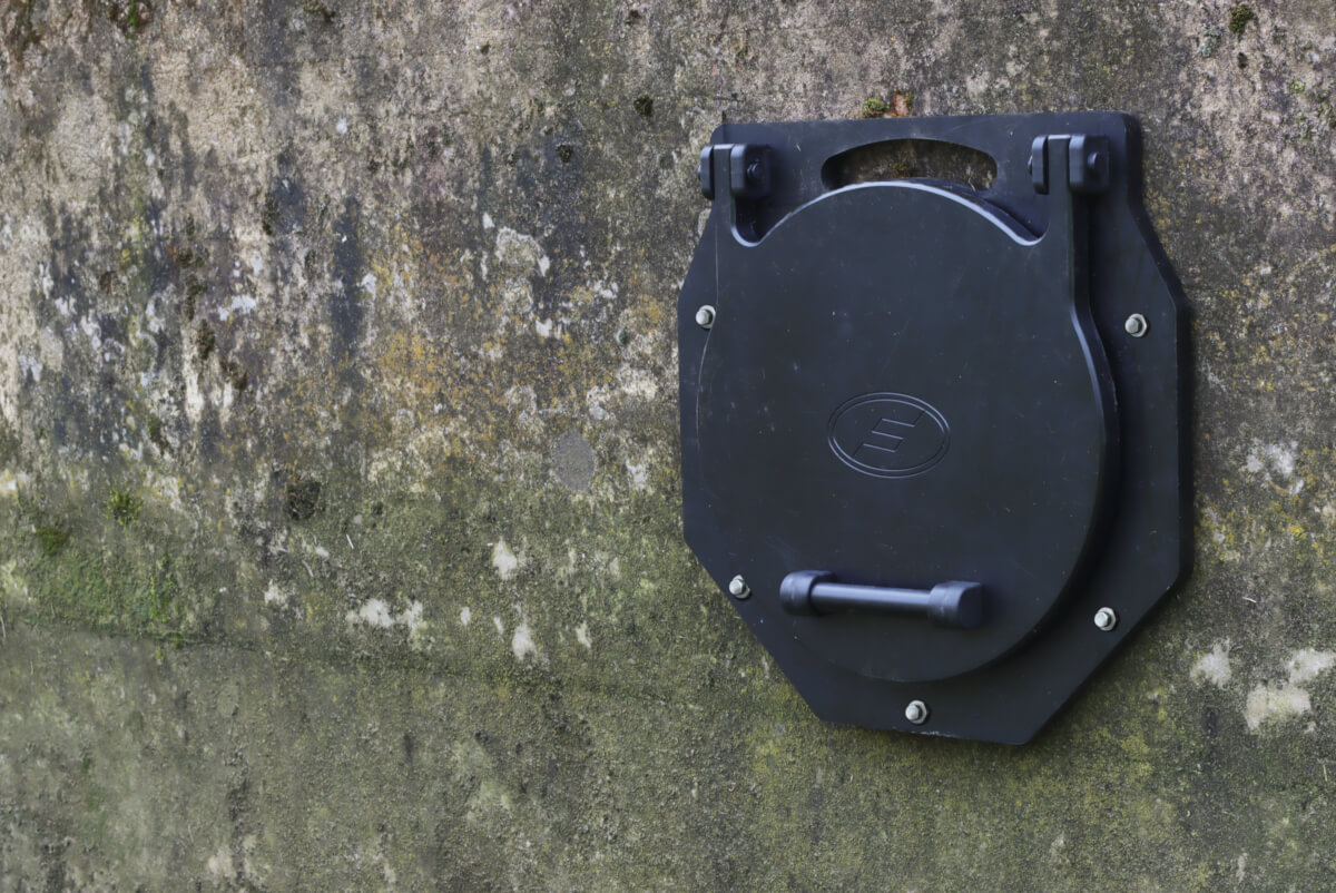
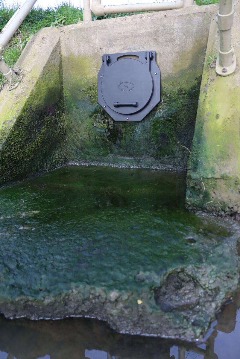
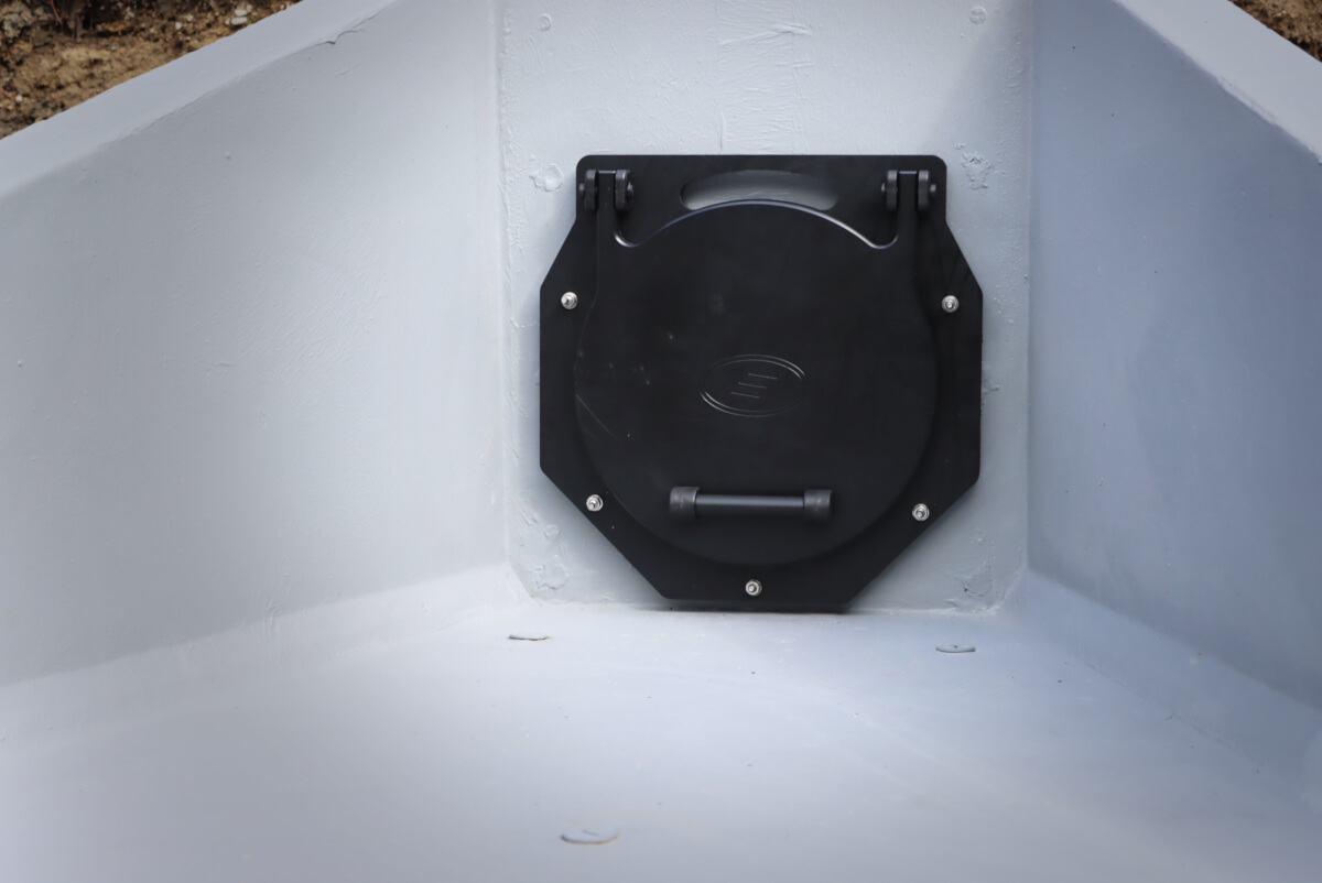
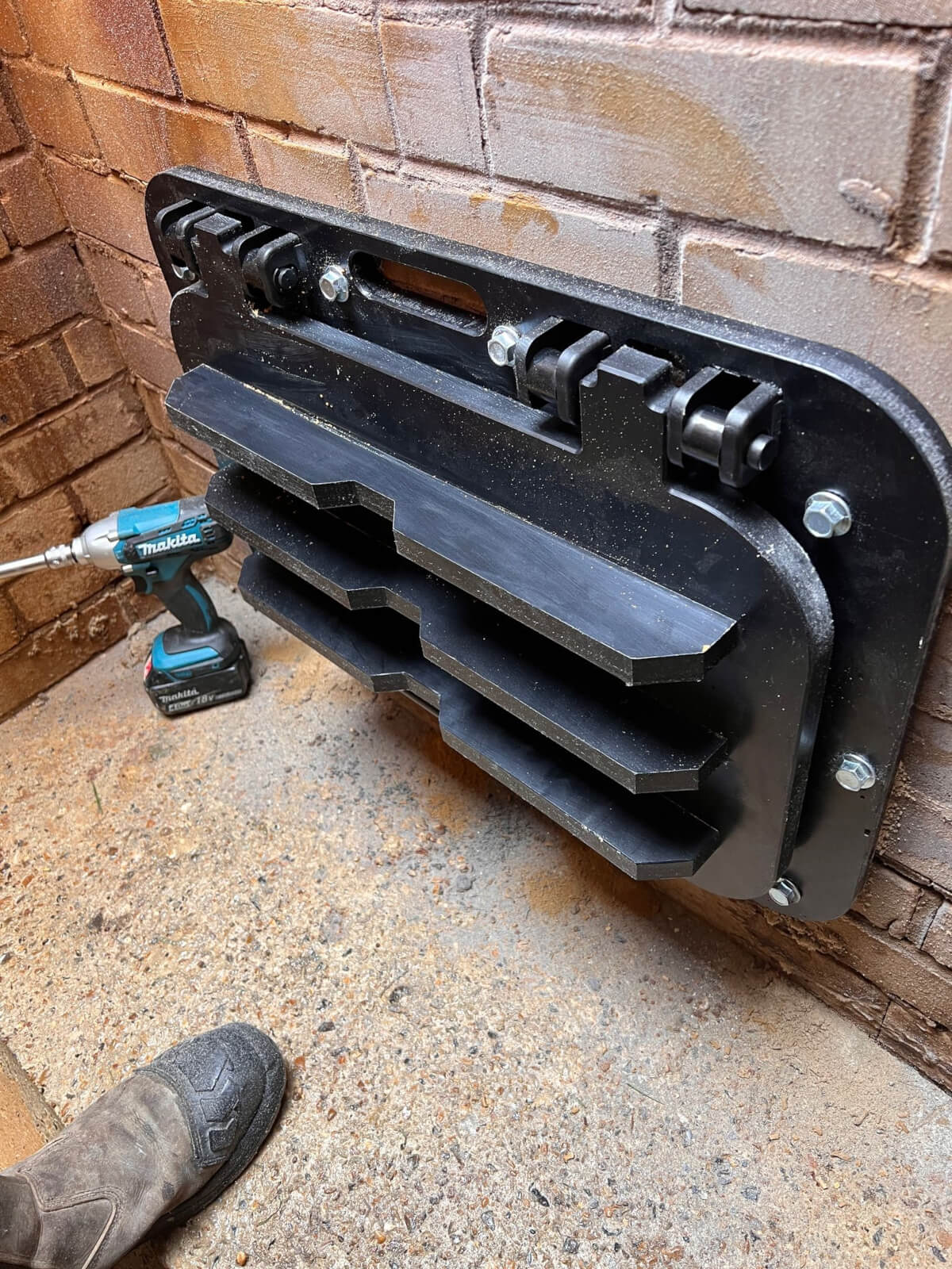
A Wall Mounted Flap Valve is a passive non-return valve designed to prevent backflow in drainage systems, particularly in environments prone to variable water levels such as rivers, estuaries, and flood-prone areas.
These valves are affixed directly to a flat wall surface, typically at the end of an outfall pipe, with their hinges positioned at the top (12 o’clock) to allow the flap to open under minimal forward flow and close securely when flow reverses.
Fernco’s Wall Mounted Flap Valves are constructed from High-Molecular-Weight Polyethylene (HMWPE 500) and marine grade 316 stainless steel, providing a strong yet lightweight structure that is corrosion and chemical resistant, meaning the Flap Valve has superior UV stability and impact resistance.
The Integrated EPDM seals ensure superior performance up to 7mWc without the need for additional sealants to be applied on site, ensuring consistent performance on every installation.
Available in sizes ranging from DN100 to DN1500 Fernco’s Wall Mounted Flap Valves are built to exceed standards such as DIN 19569-4 and BS7775, offering long service life with minimal maintenance.


| Product Code | DN | A (mm) | B (mm) | C (mm) | D (mm) | E (mm) | F (mm) | G (mm) | Mounting Hole PCD (mm) | Pressure (mwc) | Weight (kg) |
|---|---|---|---|---|---|---|---|---|---|---|---|
| FV100 | 100 | 212 | 235 | 77 | 129 | 106 | 207 | 56 | 183 | 7 | 1 |
| FV125 | 125 | 254 | 268 | 77 | 142 | 127 | 233 | 65 | 225 | 7 | 2 |
| FV150 | 150 | 274 | 291 | 79 | 154 | 137 | 248 | 62 | 240 | 7 | 2 |
| FV200 | 200 | 341 | 349 | 79 | 179 | 170 | 298 | 71 | 312 | 7 | 3 |
| FV225 | 225 | 351 | 367 | 79 | 191 | 176 | 322 | 63 | 315 | 7 | 3 |
| FV250 | 250 | 379 | 392 | 79 | 202 | 190 | 346 | 65 | 350 | 7 | 3 |
| FV300 | 300 | 429 | 442 | 79 | 228 | 214 | 396 | 65 | 400 | 7 | 4 |
| FV350 | 350 | 499 | 517 | 79 | 268 | 249 | 472 | 74 | 460 | 7 | 6 |
| FV400 | 400 | 544 | 565 | 79 | 293 | 272 | 522 | 72 | 515 | 7 | 7 |
| FV450 | 450 | 594 | 615 | 79 | 318 | 297 | 572 | 72 | 565 | 7 | 8 |
| FV500 | 500 | 649 | 667 | 99* | 343 | 324 | 622 | 75 | 620 | 7 | 10 |
| FV600 | 600 | 754 | 770 | 99* | 393 | 377 | 721 | 77 | 725 | 7 | 14 |
| FV700 | 700 | 895 | 1080** | 134* | 632** | 448 | 961 | 98 | 850 | 7 | 37 |
| FV800 | 800 | 995 | 1180** | 134* | 682** | 498 | 1061 | 98 | 950 | 7 | 44 |
| FV900 | 900 | 1095 | 1280** | 134* | 732** | 548 | 1161 | 98 | 1050 | 7 | 52 |
| FV1000 | 1000 | 1195 | 1380** | 134* | 782** | 598 | 1261 | 98 | 1150 | 7 | 60 |
| FV1100 | 1100 | 1410 | 1592** | 128*** | 886** | 705 | 1450 | 155 | 1330 | 7 | 85 |
| FV1200 | 1200 | 1510 | 1692** | 128*** | 936** | 755 | 1550 | 155 | 1430 | 7 | 95 |
| FV1300 | 1300 | 1610 | 1792** | 128*** | 986** | 805 | 1650 | 155 | 1530 | 7 | 106 |
| FV1400 | 1400 | 1710 | 1892** | 128*** | 1036** | 855 | 1750 | 155 | 1630 | 7 | 116 |
| FV1500 | 1500 | 1810 | 1992** | 128*** | 1086** | 905 | 1850 | 155 | 1730 | 7 | 128 |
* Dimension taken from the back of the wall plate to front plate strengthening ribs.
** These values are taken from the top of the lifting bracket.
*** Dimension taken from the back of the wall plate to the front edge of lifting eye.


- 1. Offer the Flap Valve to the wall in the desired fixing position, ensuring the hinges are at 12 o’clock.
- 2. Mark the drill positions where the wall mounting holes are present and use a spirit level to make sure the Flap Valve is straight.
- 3. Remove the Flap Valve and drill holes where marked using a suitable drill. Use the correct size drill bit as indicated in the table below. Ensure the hole depth is consistent with the requirements indicated in the table below.
- 4. Dust and debris must be cleaned from all drilled holes and the wall surface.
- 5. Insert the chemical capsules into the hole.
- 6. Using a suitable drill, drill the bolts provided into the holes and chemical capsules, until the depth of the hole has been reached.
- 7. Detach the drill from the bolt and remove excess residue from around the hole. Leave the chemical to cure, curing time is indicated in the table below.
- 8/9. Offer the Flap Valve over the bolts, tighten on the supplied washers and nuts to the recommended torque as given in the table below.
Wall Mounting Kit Installation Requirements
| Bolt Size | Drill Bit Required | Drilled Depth | Recommended Tightening Torque |
|---|---|---|---|
| M8 | 10mm | 80mm | 4Nm |
| M12 | 14mm | 100mm | 8Nm |
Chemical Capsule Cure Time
| Temp °C | -15 to -10 | -9 to -5 | -4 to 0 | 1 to 5 | 6 to 10 | 11 to 20 | 21 to 30 | 31 to 40 |
|---|---|---|---|---|---|---|---|---|
| Cure Time | 30h | 16h | 10h | 45min | 30min | 20min | 5min | 3min |
Spigot Mounted Flap Valve
-
Description
-
Technical Specifications
-
Installation Guides
-
Downloads
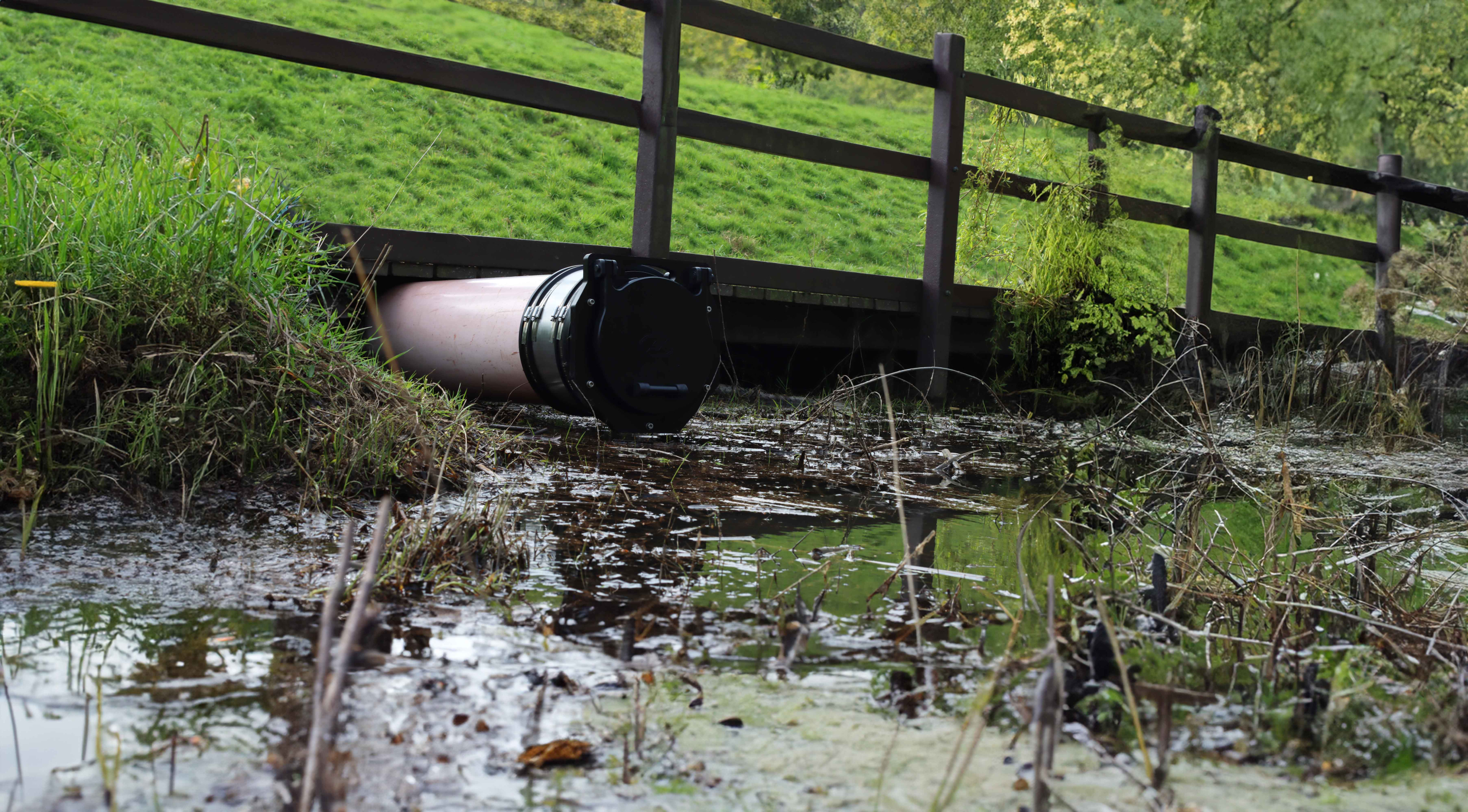
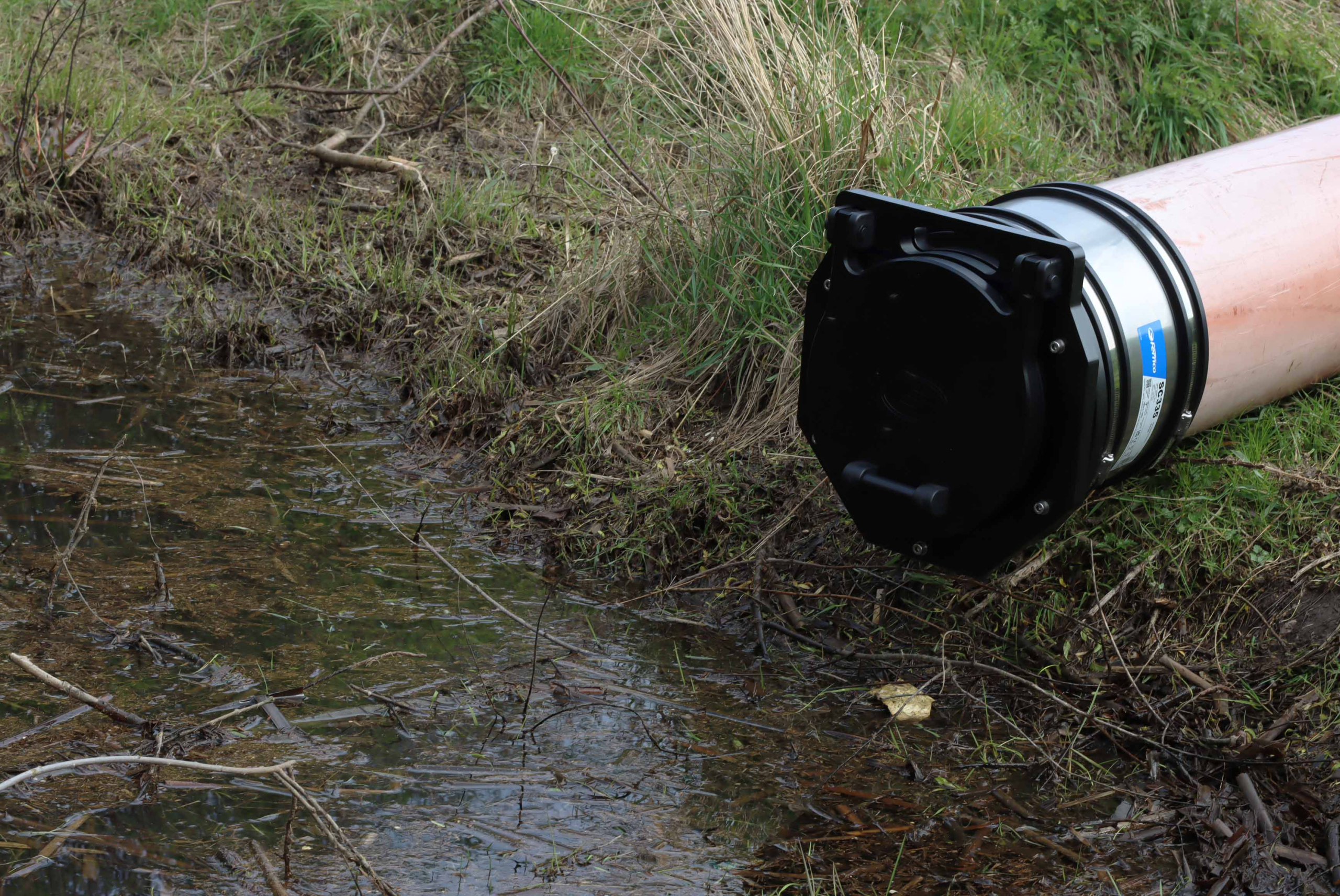
A Spigot Mounted Flap Valve is a passive non-return tidal valve designed to be connected directly to the end of a drainage pipe, providing reliable backflow prevention in systems exposed to surface water, stormwater, or tidal influence.
Fernco’s Spigot Mounted Flap Valves are constructed from High-Molecular-Weight Polyethylene (HMWPE 500) and marine grade 316 stainless steel, providing a strong yet lightweight structure that is corrosion and chemical resistant, providing superior UV stability and impact resistance.
These valves are installed either by using our Fernco shear-banded coupling for enhanced stability and flow performance or by inserting the spigot into the pipe with an EPDM sealing tape for an internal compression fit.
The flap opens under minimal forward flow and seals automatically under reverse pressure. The Integrated EPDM seals ensure superior performance up to 7mWc. Connect with a Fernco Shear-banded coupling to ensure consistent performance on every installation.
The Fernco Spigot Mounted Flap Valve is manufactured with a 10° Valve inclination, giving suitability in tidal applications, turbulent flow or to counter any connecting pipework gradient.
Available in sizes ranging from DN100 to DN630, Fernco’s Spigot Mounted Flap Valves are built to exceed standards such as DIN 19569-4 and BS7775, offering dependable protection with straightforward installation and minimal maintenance.


| Product Code | DN | Spigot OD (mm) | Spigot ID (mm) | A (mm) | B (mm) | C (mm) | D (mm) | E (mm) | Pressure (mwc) | Weight (kg) |
|---|---|---|---|---|---|---|---|---|---|---|
| FVS90 | 100 | 90 | 83 | 212 | 235 | 125 | 264 | 234 | 7 | 2 |
| FVS110 | 110 | 110 | 102 | 212 | 235 | 125 | 267 | 234 | 7 | 2 |
| FVS125 | 125 | 125 | 115 | 254 | 268 | 130 | 267 | 260 | 7 | 3 |
| FVS140 | 150 | 140 | 123 | 254 | 268 | 130 | 271 | 260 | 7 | 3 |
| FVS160 | 160 | 160 | 148 | 274 | 291 | 135 | 279 | 274 | 7 | 3 |
| FVS180 | 200 | 180 | 159 | 274 | 291 | 135 | 277 | 274 | 7 | 4 |
| FVS200 | 225 | 200 | 184 | 340 | 349 | 144 | 284 | 327 | 7 | 5 |
| FVS225 | 250 | 225 | 211 | 351 | 367 | 146 | 288 | 350 | 7 | 5 |
| FVS250 | 280 | 250 | 235 | 379 | 392 | 150 | 293 | 374 | 7 | 6 |
| FVS280 | 300 | 280 | 263 | 379 | 392 | 151 | 296 | 376 | 7 | 6 |
| FVS315 | 350 | 315 | 300 | 429 | 442 | 157 | 300 | 425 | 7 | 7 |
| FVS355 | 400 | 355 | 333 | 499 | 517 | 167 | 309 | 490 | 7 | 10 |
| FVS400 | 450 | 400 | 375 | 544 | 565 | 173 | 307 | 543 | 7 | 13 |
| FVS450 | 500 | 450 | 422 | 594 | 615 | 178 | 369 | 597 | 7 | 15 |
| FVS500 | 525 | 500 | 469 | 649 | 667 | 195* | 378* | 648 | 7 | 18 |
| FVS560 | 600 | 560 | 526 | 685 | 698 | 199* | 393* | 673 | 7 | 20 |
| FVS630 | 630 | 630 | 591 | 754 | 770 | 224* | 405* | 748 | 7 | 26 |
* Dimension taken from end of spigot to front plate strengthening ribs.
Spigot mounted Flap Valves can be connected to a pipe in two ways:
- By using a Fernco Shear banded coupling to connect the spigot flap valve to the connecting pipe, this method will offer superior stability of the valve. The valve can be sized specific to the connecting pipe’s outside diameter and therefore remove the need to seal inside the pipeline and restrict bore.
- By inserting the spigot inside of the pipe and securing into position using a supplied EPDM sealing tape. For this option simply select the spigot size (column Spigot ID) which will fit inside the pipe.
Please ensure supplied OD and ID measurements are accurate so the correct bush can be specified with the Spigot Flap Valve.
Installation Guide: Spigot Mounted Flap Valve using Shear Banded Coupling


- 1. Ensure the pipe has a straight/flat end face.
- 2. Clean the outer pipe surface leaving a smooth surface for the coupling to seal onto.
- 3. Measure the coupling width, mark half this measurement on both the flap valve spigot and connecting pipe.
- 4. If using a bush slide the bush onto the Flap Valve spigot until the edge of the bush and the marked line are flush.
- 5. Slide the coupling over the bush until the end faces are flush, hand tighten the end clamp. If no bush is required slide the coupling onto the spigot until the edge of the coupling and marked line are flush, hand tighten the end clamp.
- 6. Butt the Flap Valve spigot up to the main pipe, the coupling should now be in-line with the line previously marked on the pipe. Ensure the Flap Valve is in the correct orientation (hinge mechanism at 12 o’clock), hand tighten the end clamp.
- 7. Tighten all clamp bands to the recommended torque (see coupling label) in sequence across the width of the coupling starting with the central shear band.
Installation Guide: Spigot Mounted Flap Valve using Sealing Tape


- 1. Ensure the pipe end has a straight/flat surface for mounting.
- 2. Clean away any debris from the internal surface of the pipe.
- 3. Take the Sealing tape supplied with the Flap Valve, peel away the self-adhesive backing and wrap around the external surface of the Flap Valve spigot.
- 4. Ensure the outside diameter of the tape is now approximately 5mm larger than the internal diameter of the pipe to ensure a compressive fit.
- 5. Insert the spigot section of the Flap Valve into the pipe until the pipe end is flush with the Flap Valves back plate. When inserting ensure the Flap Valve hinge mechanism is at 12 o’clock.
Sealing Tape Sizes
| Finished Product | Part Code | Description | Quantity (Metres) |
|---|---|---|---|
| EPDM Sealing Strip | FVSMS-01 | EPDM Spigot Sealing Strip For Flap Valve Spigots DN100, DN125, DN150 | 2.5m |
| EPDM Sealing Strip | FVSMS-02 | EPDM Spigot Sealing Strip For Flap Valve Spigots DN200, DN225, DN250 | 5m |
| EPDM Sealing Strip | FVSMS-03 | EPDM Spigot Sealing Strip For Flap Valve Spigots DN300, DN350, DN400 | 7.5m |
| EPDM Sealing Strip | FVSMS-04 | EPDM Spigot Sealing Strip For Flap Valve Spigots DN450, DN500, DN600 | 10m |
Tidal Flange Mounted Flap Valve
-
Description
-
Technical Specifications
-
Installation Guide
-
Downloads
A Tidal Flange Mounted Flap Valve is a passive non-return tidal valve designed to be connected directly to a flange located at the end of a drainage pipe, providing reliable backflow prevention in systems exposed to surface water, stormwater, or tidal influence.
Fernco’s Tidal Flange Mounted Flap Valves are constructed from High-Molecular-Weight Polyethylene (HMWPE 500) and marine grade 316 stainless steel, providing a strong yet lightweight structure that is corrosion and chemical resistant, providing superior UV stability and impact resistance.
These valves are secured to standard pipe flanges using industry-recognised drilling patterns such as BS4504, ISO 7005 (DIN), AS2129, and AS4087, ensuring compatibility across a wide range of infrastructure systems.
The flap opens under minimal forward flow and seals automatically under reverse pressure. The Integrated EPDM seals ensure superior performance up to 7mWc.
The Fernco Flange Tidal Mounted range is manufactured with a 10° valve inclination, giving suitability in tidal applications, turbulent flow or to counter any connecting pipework gradient.
Available in sizes ranging from DN100 to DN1400, Fernco’s Flange Mounted Flap Valves are built to exceed standards such as DIN 19569-4 and BS7775, offering dependable protection with straightforward installation and minimal maintenance.


| Pipe DN | Flange Options | Description |
|---|---|---|
| DN100 | FVTF100-1 | DN100 BS4504 / ISO 7005 (DIN) PN10/PN16 |
| FVTF100-2 | DN100 AS2129 Table C/D AS4087 PN14/PN16 | |
| DN125 | FVTF125-1 | DN125 BS4504 / ISO 7005 (DIN) PN10/PN16 |
| FVTF125-2 | DN125 AS2129 Table C/D/E AS4087 PN14/PN16 | |
| DN150 | FVTF150-1 | DN150 BS4504 / ISO 7005 (DIN) PN10/PN16 |
| FVTF150-2 | DN150 AS2129 Table C/D AS4087 PN14/PN16 | |
| DN200 | FVTF200-1 | DN200 BS4504 / ISO 7005 (DIN) PN10 |
| FVTF200-2 | DN200 BS4504 / ISO 7005 (DIN) PN16 | |
| FVTF200-3 | DN200 AS2129 Table C/D AS4087 PN14/PN16 | |
| DN250 | FVTF250-1 | DN250 BS4504 / ISO 7005 (DIN) PN10 |
| FVTF250-2 | DN250 BS4504 / ISO 7005 (DIN) PN16 | |
| FVTF250-3 | DN250 AS2129 Table C/D AS4087 PN14/PN16 | |
| DN300 | FVTF300-1 | DN300 BS4504 / ISO 7005 (DIN) PN10 |
| FVTF300-2 | DN300 BS4504 / ISO 7005 (DIN) PN16 | |
| FVTF300-3 | DN300 AS2129 Table C/D/E AS4087 PN14/PN16 | |
| DN350 | FVTF350-1 | DN350 BS4504 / ISO 7005 (DIN) PN10 |
| FVTF350-2 | DN350 BS4504 / ISO 7005 (DIN) PN16 | |
| FVTF350-3 | DN350 AS2129 Table C/D/E | |
| DN400 | FVTF400-1 | DN400 BS4504 / ISO 7005 (DIN) PN10 |
| FVTF400-2 | DN400 BS4504 / ISO 7005 (DIN) PN16 | |
| FVTF400-3 | DN400 AS2129 Table C/D/E AS4087 PN14/PN16 | |
| DN450 | FVTF450-1 | DN450 BS4504 / ISO 7005 (DIN) PN10 |
| FVTF450-2 | DN450 AS2129 Table C/D/E AS4087 PN14/PN16 | |
| FVTF450-3 | DN450 AS2129 Table C/D/E AS4087 PN14/PN16 | |
| DN500 | FVTF500-1 | DN500 BS4504 / ISO 7005 (DIN) PN10 |
| FVTF500-2 | DN500 BS4504 / ISO 7005 (DIN) PN16 | |
| FVTF500-3 | DN500 AS2129 Table C/D/E | |
| DN600 | FVTF600-1 | DN600 BS4504 / ISO 7005 (DIN) PN10 |
| FVTF600-2 | DN600 BS4504 / ISO 7005 (DIN) PN16 | |
| FVTF600-3 | DN600 AS2129 Table C/D AS4087 PN14/PN16 | |
| DN700 | FVT700-1 | DN700 ISO7005 PN10 |
| FVT700-2 | DN700 ISO7005 PN16 | |
| FVT700-3 | DN700 AS2129 Table D | |
| DN900 | FVT900-1 | DN900 ISO7005 PN10 |
| FVT900-2 | DN900 ISO7005 PN16 | |
| FVT900-3 | DN900 AS2129 Table D | |
| DN1050 | FVT1050-1 | DN1050 ISO7005 PN10 |
| FVT1050-2 | DN1050 ISO7005 PN16 | |
| FVT1050-3 | DN1050 AS2129 Table D | |
| DN1200 | FVT1200-1 | DN1200 ISO7005 PN10 |
| FVT1200-2 | DN1200 ISO7005 PN16 | |
| FVT1200-3 | DN1200 AS2129 Table D | |
| DN1400 | FVT1400-1 | DN1400 ISO7005 PN10 |
| FVT1400-2 | DN1400 ISO7005 PN16 | |
| FVT1400-3 | DN1400 AS2129 Table D |
Product drawings available for approval at quoting stage.
Other flange adaptors can be manufactured on request.
- 1. Attach the Tidal Flange Mounted Flap Valve to the desired flange, ensuring that the hinges of the flap valve are level.
- 2. Tighten the fixings as per the flange specification, the flange fixing kit is not provided.

Tidal Wall Mounted Flap Valve
-
Description
-
Technical Specifications
-
Installation Guide
-
Downloads
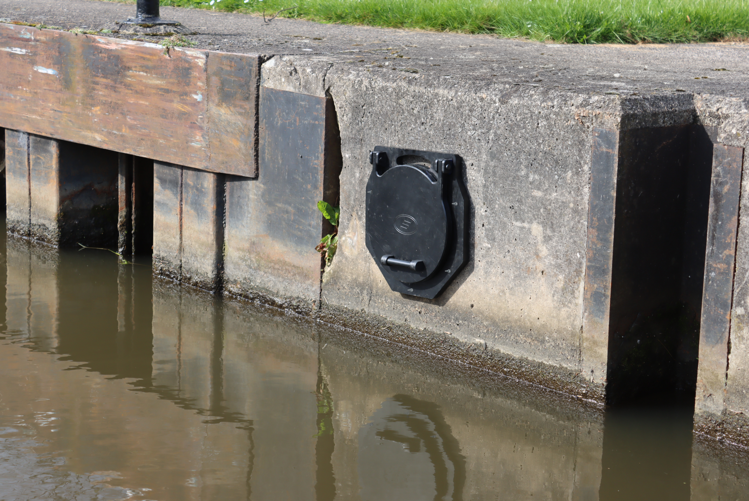
A Tidal Wall Mounted Flap Valve is a passive non-return tidal valve designed to be connected directly to the end of a drainage outlet located at a wall or flat surface, providing reliable backflow prevention in systems exposed to surface water, stormwater, or tidal influence.
The Tidal Valve’s construction incorporates a 10° inclination, ensuring continuous even compression of the seal, even when submerged or under conditions of turbulent back pressure. This maintains the flap door in a naturally closed and seated position, unaffected by external hydraulic fluctuations. Consequently, the valve delivers consistent operational performance, effectively preventing backflow and preserving optimal system performance.
Fernco’s Tidal Wall Mounted Flap Valves are constructed from High-Molecular-Weight Polyethylene (HMWPE 500) and marine grade 316 stainless steel, providing a strong yet lightweight structure that is corrosion and chemical resistant, providing superior UV stability and impact resistance.
Available in sizes ranging from DN100 to DN1400, Fernco’s Tidal Wall Mounted Flap Valves are built to exceed standards such as DIN 19569-4 and BS7775, offering dependable protection with straightforward installation and minimal maintenance.


| Product Code | DN | A (mm) | B (mm) | C (mm) | D (mm) | E (mm) | F (mm) | Mounting Hole PCD (mm) | Pressure (mwc) | Weight (kg) |
|---|---|---|---|---|---|---|---|---|---|---|
| FVT100 | 100 | 212 | 235 | 267 | 212 | 102 | 376 | 183 | 7 | 3 |
| FVT150 | 150 | 274 | 291 | 279 | 260 | 148 | 419 | 221 | 7 | 4 |
| FVT200 | 200 | 351 | 267 | 288 | 340 | 211 | 493 | 283 | 7 | 6 |
| FVT225 | 225 | 379 | 392 | 288 | 370 | 235 | 517 | 311 | 7 | 7 |
| FVT250 | 250 | 379 | 392 | 296 | 385 | 263 | 521 | 333 | 7 | 7 |
| FVT300 | 300 | 429 | 442 | 300 | 450 | 300 | 567 | 383 | 7 | 9 |
| FVT400 | 400 | 544 | 565 | 367 | 595 | 422 | 788 | 523 | 7 | 17 |
| FVT500 | 500 | 685 | 698 | 393* | 695 | 526 | 868 | 628 | 7 | 24 |
| FVT600 | 600 | 754 | 770 | 405* | 780 | 591 | 930 | 705 | 7 | 29 |
| FVT750 | 750 | 995 | 1178 | 742* | 1000 | 750 | 1506 | 900 | 7 | 72 |
| FVT900 | 900 | 1095 | 1299 | 750* | 1150 | 900 | 1592 | 1050 | 7 | 89 |
| FVT1050 | 1050 | 1410 | 1592 | 759* | 1300 | 1050 | 1864 | 1200 | 5 | 120 |
| FVT1200 | 1200 | 1510 | 1694 | 768* | 1500 | 1200 | 1955 | 1400 | 5 | 161 |
| FVT1400 | 1400 | 1750 | 1904 | 785* | 1750 | 1400 | 2138 | 1650 | 5 | 215 |
* Dimension taken from the back of the wall plate to front plate rib.
- 1. Offer the Flap Valve to the wall in the desired fixing position, ensuring the top fixing bolt is at 12 o’clock.
- 2. Mark on the wall the drill positions where the wall mounting holes are present.
- 3. Remove the Flap Valve and drill holes where marked using a suitable drill and the correct size drill bit as shown in the table below. Ensure the hole depth for all holes is consistent as shown in the table below.
- 4. Dust and debris must be cleaned from all drilled holes and the wall surface.
- 5. Insert the chemical capsules into the hole.
- 6. Using a suitable drill, drill the bolts provided into the holes and chemical capsules, until the depth of the hole has been reached.
- 7. Detach the drill from the bolt and remove excess residue from around the hole. Leave the chemical to cure, curing time is shown in the table below.
- 8. Offer the Flap Valve over the bolts, tighten on the supplied washers and nuts to the recommended torque as shown in the table below.
Wall Mounting Kit Installation Requirements
| Bolt Size | Drill Bit Required | Drilled Depth | Recommended Tightening Torque |
|---|---|---|---|
| M8 | 10mm | 80mm | 4Nm |
| M12 | 14mm | 100mm | 8Nm |
Chemical Capsule Cure Time
| Temp °C | -15 to -10 | -9 to -5 | -4 to 0 | 1 to 5 | 6 to 10 | 11 to 20 | 21 to 30 | 31 to 40 |
|---|---|---|---|---|---|---|---|---|
| Cure Time | 30h | 16h | 10h | 45min | 30min | 20min | 5min | 3min |
Curved Back Flap Valve
-
Description
-
Technical Specifications
-
Installation Guide
-
Downloads
A Curved Back Flap Valve is a passive non-return valve designed to prevent backflow in drainage systems, particularly in environments prone to variable water levels such as rivers, estuaries, and flood-prone areas. Curved Back Flap Valves are required when installing in curved chambers.
These valves are affixed directly to a curved wall surface, typically at the end of an outfall pipe, with their hinges positioned at the top (12 o’clock) to allow the flap to open under minimal forward flow and close securely when flow reverses.
Fernco’s Curved Back Flap Valves are constructed from High-Molecular-Weight Polyethylene (HMWPE 500) and marine grade 316 stainless steel, providing a strong yet lightweight structure that is corrosion and chemical resistant, meaning the Flap Valve has superior UV stability and impact resistance.
The Integrated EPDM seals ensure superior performance up to 7mWc without the need for additional sealants to be applied on site, ensuring consistent performance on every installation.
Available in sizes ranging from DN100 to DN300 Fernco’s Curved Back Flap Valves are built to exceed standards such as DIN 19569-4 and BS7775, offering long service life with minimal maintenance.


| Product Code | Diameter (Ø) | Chamber Diameter Range (mm) | A (mm) | B (mm) | C (mm) | D (mm) | E (mm) | F (mm) | G (mm) | Pressure (mWC) | Weight (kg) |
|---|---|---|---|---|---|---|---|---|---|---|---|
| FVCB100-1 | 100 | 1000-1600 | 250 | 235 | 127 | 129 | 234 | 257 | 56 | 7 | 3 |
| FVCB100-2 | 100 | 1601-2100 | 250 | 235 | 117 | 129 | 234 | 247 | 56 | 7 | 2 |
| FVCB150-1 | 150 | 1000-1600 | 300 | 268 | 128 | 154 | 260 | 346 | 62 | 7 | 4 |
| FVCB150-2 | 150 | 1601-2100 | 300 | 268 | 129 | 154 | 260 | 248 | 52 | 7 | 4 |
| FVCB200-1 | 200 | 1000-1600 | 350 | 291 | 159 | 170 | 274 | 378 | 71 | 7 | 7 |
| FVCB200-2 | 200 | 1601-2100 | 350 | 291 | 129 | 170 | 274 | 348 | 71 | 7 | 5 |
| FVCB225-1 | 225 | 1000-1600 | 375 | 349 | 159 | 176 | 327 | 402 | 63 | 7 | 7 |
| FVCB225-2 | 225 | 1601-2100 | 375 | 367 | 128 | 176 | 350 | 371 | 63 | 7 | 5 |
| FVCB250-1 | 250 | 1000-1600 | 400 | 392 | 158 | 190 | 374 | 425 | 65 | 7 | 8 |
| FVCB250-2 | 250 | 1601-2100 | 400 | 392 | 157 | 190 | 376 | 424 | 65 | 7 | 8 |
| FVCB300-1 | 300 | 1000-1600 | 450 | 442 | 160 | 214 | 425 | 477 | 65 | 7 | 9 |
| FVCB300-2 | 300 | 1601-2100 | 450 | 517 | 158 | 214 | 490 | 475 | 65 | 7 | 10 |
- 1. Offer the Curved Back Adaptor to the wall in the desired fixing position, ensuring the hinges are at 12 o’clock.
- 2. Mark the drill positions where the wall mounting holes are present, use a spirit level to ensure the Curved Back Adaptor is level.
- 3. Remove the Curved Back Adaptor and drill holes where marked using a suitable hammer drill. Use the correct size drill bit as indicated in table 1. Ensure the hole depth is consistent with the requirements indicated in table 1. Dust and debris must be cleaned from all drilled holes and the wall surface.
- 4. Carefully insert the resin capsules into the drilled holes.
- 5. Attach the threaded rod into the chuck of a suitable hammer drill, drive the threaded rod into the capsule until it reaches the bottom of the hole.
- 6. Detach the drill from the threaded rod and remove excess residue from around the hole. Leave the resin to cure, curing time is indicated in table 2.
- 7. Offer the Curved Back Adaptor then the Flap Valve over the threaded rods, tighten the supplied washers and nuts to the recommended torque as given in table 1.
Wall Mounting Kit Installation Requirements
| Bolt Size | Drill Bit Required | Drilled Depth | Recommended Tightening Torque |
|---|---|---|---|
| M8 | 10mm | 80mm | 4Nm |
| M12 | 14mm | 100mm | 8Nm |
Chemical Capsule Cure Time
| Temp °C | -15 to -10 | -9 to -5 | -4 to 0 | 1 to 5 | 6 to 10 | 11 to 20 | 21 to 30 | 31 to 40 |
|---|---|---|---|---|---|---|---|---|
| Cure Time | 30h | 16h | 10h | 45min | 30min | 20min | 5min | 3min |
-
Overview
-
Mounting Options
-
Videos
-
Gallery
-
Downloads
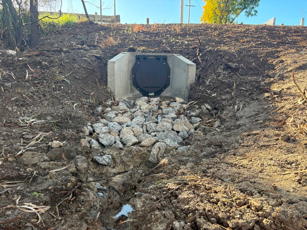
The Fernco HDPE Flap Valve is a one-way passive non-return valve engineered to prevent backflow from endangering commercial and residential drainage.
Installed at the discharge end of pipelines or culverts, it allows water to exit freely while automatically closing against reverse pressure, safeguarding the upstream system from flooding or contamination.
Manufactured from High-Molecular Weight Polyethylene (HMWPE / PE500), the Fernco Flap Valve range delivers exceptional durability and reliability, even in the harshest marine environments. The HMWPE construction makes the Flap Valves lightweight for ease of handling and installation yet robust enough to withstand the demands of tidal forces, submersion, and flood-prone environments. Compared to cast iron alternatives, the Fernco Flap Valves offer a significant reduction in opening pressure, minimising the volume of stagnant water retained behind the gate while providing excellent long-term corrosion resistance.
The product range includes configurations for wall, spigot, tidal, and flange mounting options, ensuring that they can be installed in every environment. The Flap Valves use a patented sealing technology that performs under both low and high pressures while eliminating the variance in installation quality. An integrated EPDM sponge seal ensures a watertight seal between the mounting surface and valve, removing the need for any additional sealing materials.

Built to Perform
Engineered for Water Environments
Easy to Install & Maintain
| Wall Mounted | Spigot Mounted | Tidal Flange Mounted | Tidal Wall Mounted | Curved Back |
|---|---|---|---|---|
| FV100 | FVS100/FVS110 | FVTF100 | FVT100 | FVCB100-1/2 |
| FV125 | FVS110/FVS125 | FVTF125 | - | |
| FV150 | FVS150/FVS160 | FVTF150 | FVT150 | FVCB150-1/2 |
| FV200 | FVS200/FVS225 | FVTF200 | FVT200 | FVCB200-1/2 |
| FV225 | FVS225 | - | FVT225 | FVCB225-1/2 |
| FV250 | FVS250/FVS280 | FVTF250 | FVT250 | FVCB250-1/2 |
| FV300 | FVS280/FVS300 | FVTF300 | FVT300 | FVCB300-1/2 |
| FV350 | FVS350 | FVTF350 | - | |
| FV400 | FVS400 | FVTF400 | FVT400 | |
| FV450 | FVS450 | FVTF450 | - | |
| FV500 | FVS500 | FVTF500 | FVT500 | |
| FV600 | FVS600/FVS630 | FVTF600 | FVT600 | |
| FV700 | - | - | - | |
| FV800 | - | - | - | |
| FV900 | - | - | - | |
| FV1000 | - | - | - |
Need help with installation? Watch the videos below for clear, step-by-step guidance on how to correctly install Fernco’s Wall Mounted and Spigot Mounted Flap Valves. Whether you’re on-site or planning ahead, these quick tutorials walk you through the process and highlight key tips for a secure, trouble-free fit.
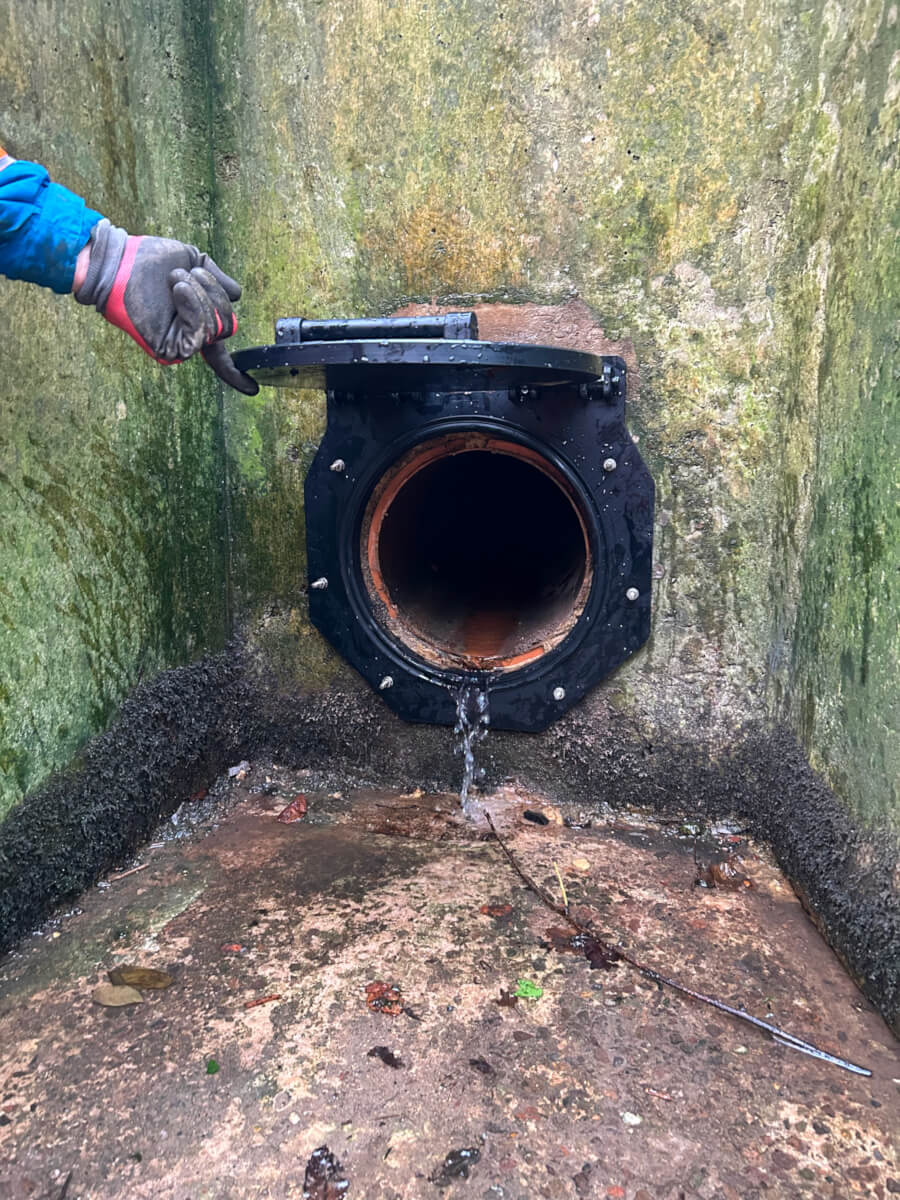
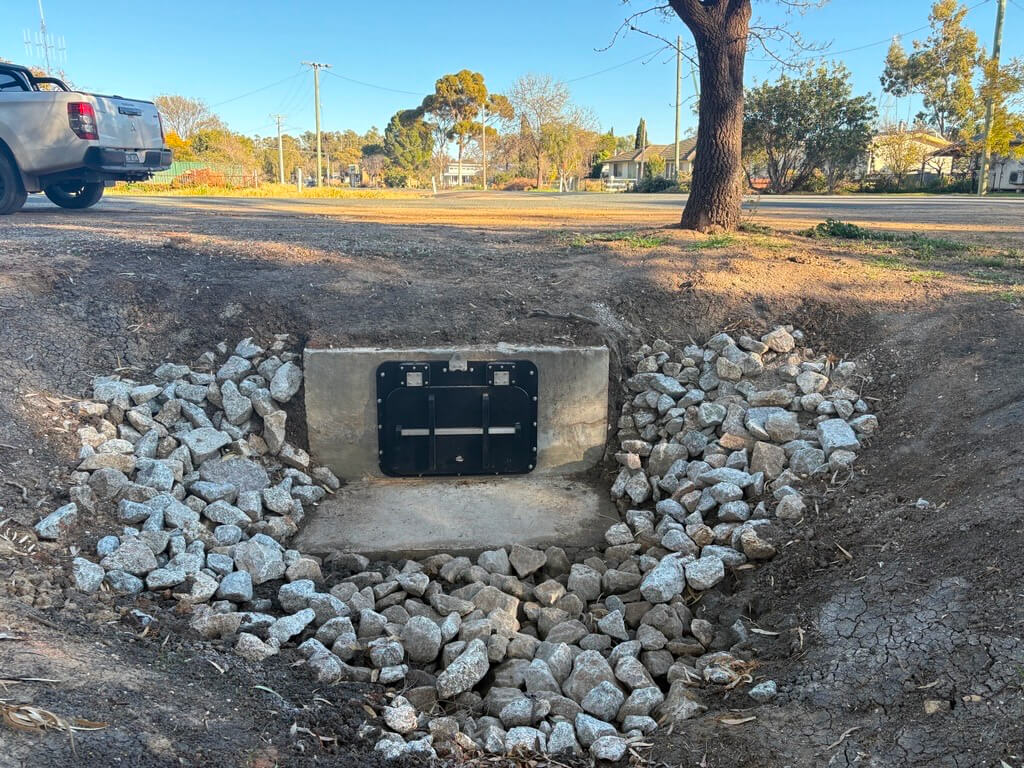
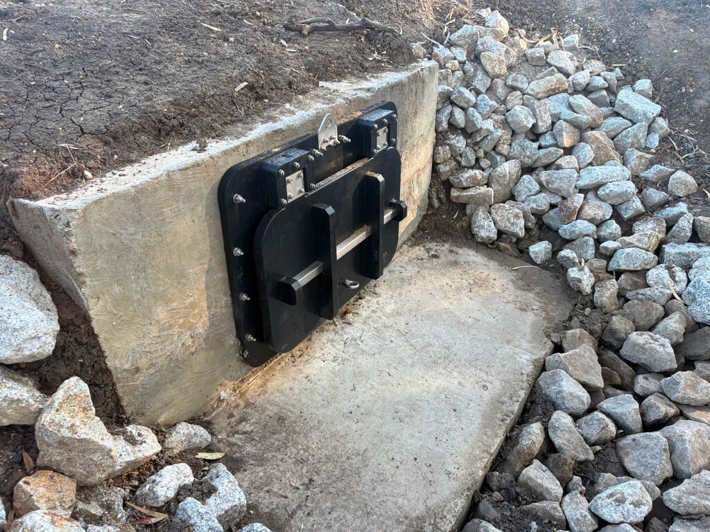
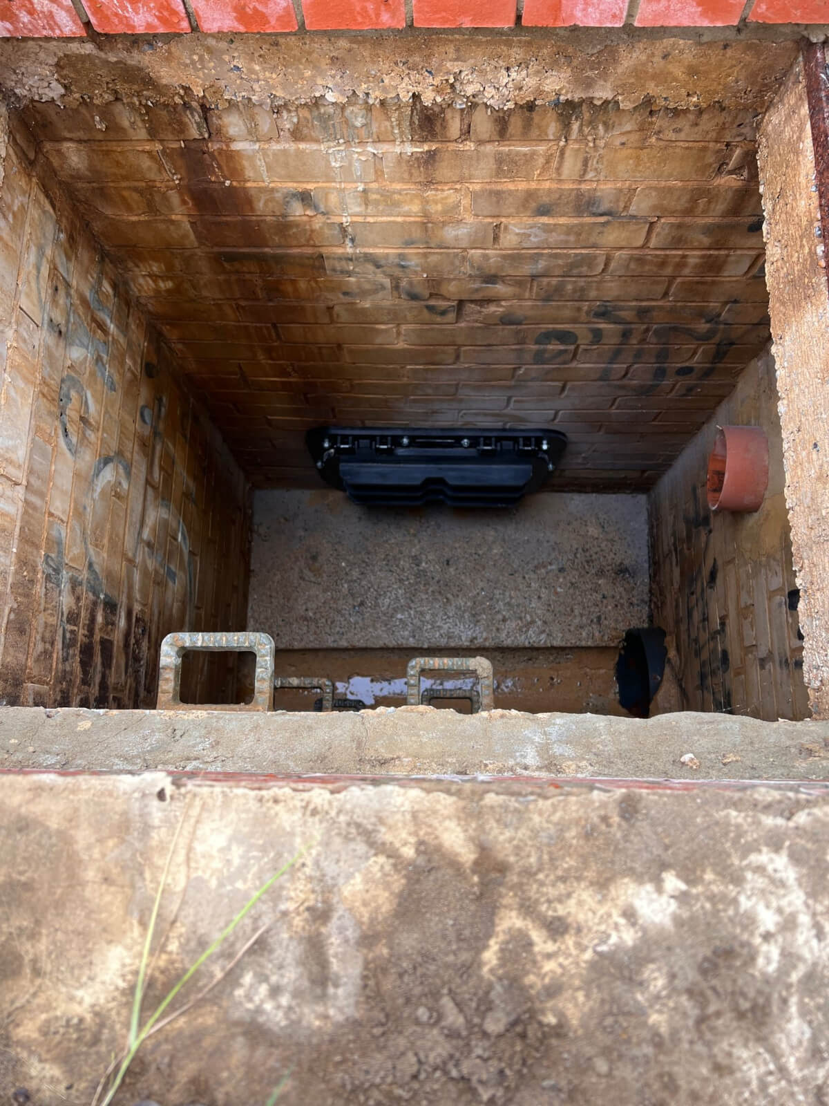
Browse the gallery below to see Fernco’s Flap Valves across the full range of mounting options, including wall mounted, spigot mounted, tidal, and flange variants. These images showcase the design, construction, and installation of each valve type, helping you visualise how they function in real-world applications.
Looking for detailed specifications and technical information? Download the Fernco Flap Valves data sheet below for a complete overview of product dimensions, materials, installation guidance, and performance characteristics — all in one convenient PDF.
To download the data sheet, simply click the button below and fill in the short form — it only takes a few seconds and gives you instant access to all the information required for specifying or installing our flap valves with confidence.

Need the full technical specification?
The complete product guide for engineers and installers.
Our datasheet includes everything you need to specify, install, or compare Fernco Flap Valves — from dimensions and pressure ratings to materials, mounting options, and performance standards. It’s the go-to reference for engineers, contractors, and consultants working in drainage, flood defence, or water infrastructure.
To access the download, just fill in the quick form provided. It only takes a moment and gives you instant access to the full PDF. Once submitted, you’ll be able to view, save, or share the datasheet whenever you need it.
Frequently Asked Questions
Related Products
Related products


Related Case Studies
Related case studies

Related Sectors
Related sectors


Got a question or need help choosing the right product for your project?
Whether you’re looking for technical advice, sizing guidance, or bespoke configurations, our team is here to help.
Simply fill out the quick enquiry form and one of our product specialists will get back to you as soon as possible.